This thread has been locked.
If you have a related question, please click the "Ask a related question" button in the top right corner. The newly created question will be automatically linked to this question.
Dear Sir,
We have started new development using TM4C129x development board. As boot loader guide explain the ROM based and Flash based boot loader but example given for only ROM based.
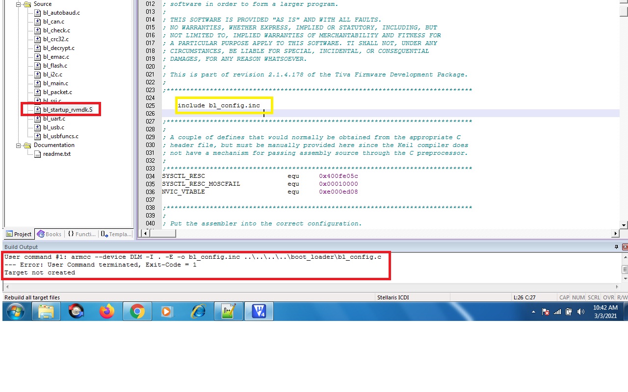
I want to implement the flash based boot loader using Keil compiler. But not able to compile project.
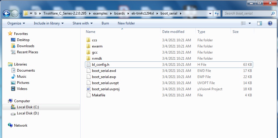
Compiler is not able to find the include bl_config.inc .
Kindly share the code which compile on keil or supporting file which keil needed.
We are attaching the bl_startup_rvmdk.S file for reference.bl_startup_rvmdk.S
Regards,
Abhijit
Hi,
For the CCS, the equivalent startup file is called bl_startup_ccs.s. In it, it includes the header file bl_config.h instead. The bl_config.h is a header file at the application level, not part of the boot_loader library. I think this is why you can't find neither the bl_config.h or bl_config.inc file in C:\ti\TivaWare_C_Series-2.2.0.295\boot_loader.
If you go to the bootlader example like C:\ti\TivaWare_C_Series-2.2.0.295\examples\boards\ek-tm4c1294xl\boot_serial (there are actually a few bootloader examples in TivaWare library), you will find the bl_config.h file. I'm also attaching here for your reference.
Dear charles,
Thanks for reply,
I have perform the following activities
1. I have dump the boot_serial.bin ( Uart enable) attached using LMFLASH loader with program address offset 0x0
The application and vector address are same as 0x4000
2. Compile the application code with offset 0x4000 and project bin file dump to the TM4c129X development board through LMflash loader with program address offset 0x4000.
Is above two process Right?
Attached also c file for reference.
3. Next step is how to update the new application code? (Should we use LMFlashloader in UART mode for new bin file)
#include <stdint.h> #include <stdbool.h> #include "inc/hw_memmap.h" #include "inc/hw_types.h" #include "inc/hw_gpio.h" #include "inc/hw_ssi.h" #include "inc/hw_sysctl.h" #include "inc/hw_epi.h" #include "inc/hw_ints.h" #include "inc/hw_nvic.h" #include "inc/hw_uart.h" #include "driverlib/debug.h" #include "driverlib/fpu.h" #include "driverlib/gpio.h" #include "driverlib/rom.h" #include "driverlib/rom_map.h" #include "driverlib/interrupt.h" #include "driverlib/pin_map.h" #include "driverlib/sysctl.h" #include "driverlib/ssi.h" #include "driverlib/uart.h" #include "utils/uartstdio.h" //***************************************************************************** // // Number of bytes to send and receive. // //***************************************************************************** #define NUM_SSI_DATA 3 //***************************************************************************** // // Passes control to the bootloader and initiates a remote software update. // // This function passes control to the bootloader and initiates an update of // the main application firmware image via UART0, Ethernet or USB depending // upon the specific boot loader binary in use. // // \return Never returns. // //***************************************************************************** void JumpToBootLoader(void) { // // We must make sure we turn off SysTick and its interrupt before entering // the boot loader! // ROM_SysTickIntDisable(); ROM_SysTickDisable(); // // Disable all processor interrupts. Instead of disabling them // one at a time, a direct write to NVIC is done to disable all // peripheral interrupts. // HWREG(NVIC_DIS0) = 0xffffffff; HWREG(NVIC_DIS1) = 0xffffffff; // // Return control to the boot loader. This is a call to the SVC // handler in the boot loader. // (*((void (*)(void))(*(uint32_t *)0x2c)))(); } //***************************************************************************** // // This function sets up UART0 to be used for a console to display information // as the example is running. // //***************************************************************************** void InitConsole(void) { // // Enable GPIO port A which is used for UART0 pins. // TODO: change this to whichever GPIO port you are using. // SysCtlPeripheralEnable(SYSCTL_PERIPH_GPIOA); // // Configure the pin muxing for UART0 functions on port A0 and A1. // This step is not necessary if your part does not support pin muxing. // TODO: change this to select the port/pin you are using. // GPIOPinConfigure(GPIO_PA0_U0RX); GPIOPinConfigure(GPIO_PA1_U0TX); // // Enable UART0 so that we can configure the clock. // SysCtlPeripheralEnable(SYSCTL_PERIPH_UART0); // // Use the internal 16MHz oscillator as the UART clock source. // UARTClockSourceSet(UART0_BASE, UART_CLOCK_PIOSC); // // Select the alternate (UART) function for these pins. // TODO: change this to select the port/pin you are using. // GPIOPinTypeUART(GPIO_PORTA_BASE, GPIO_PIN_0 | GPIO_PIN_1); // // Initialize the UART for console I/O. // UARTStdioConfig(0, 115200, 16000000); } //***************************************************************************** // // Configure SSI3 in master Freescale (SPI) mode. This example will send out // 3 bytes of data, then wait for 3 bytes of data to come in. This will all be // done using the polling method. // //***************************************************************************** int main(void) { SysCtlPeripheralEnable(SYSCTL_PERIPH_GPIOQ); InitConsole(); GPIOPinTypeGPIOInput(GPIO_PORTQ_BASE,GPIO_PIN_5); GPIOPinTypeGPIOOutput(GPIO_PORTQ_BASE,GPIO_PIN_6); while(GPIOPinRead(GPIO_PORTQ_BASE, GPIO_PIN_5) == GPIO_PIN_5) { MAP_GPIOPinWrite(GPIO_PORTQ_BASE, GPIO_PIN_6, GPIO_PIN_6); SysCtlDelay(16000000/12); MAP_GPIOPinWrite(GPIO_PORTQ_BASE, GPIO_PIN_6, 0x00); SysCtlDelay(16000000/12); } JumpToBootLoader(); }
Regards,
Abhijit
Hi,
Yes.
1. Load the boot_serial.bin (this is the bootloader) via JTAG to the flash at 0x0.
2. Select serial mode in LM flash programmer. You need to choose your COM port.
3. Load your application (your TM4C129_PQ6.bin) like below. I will suggest you start with the TivaWare boot_demo1.bin first. If it works, then move on to your own application.
Dear Charles,
Thanks for reply.
My queries
a. The above step mentioned by you in point 2 &3 for new application update ? What i understood ,Is that Right?
b.As you suggested that first try with boot_demo1. It is compatible with TM4C129X?
c. We are facing issue with compilation in keil compiler using file given(bl_startup_rvmdk.S) in bootloader folder and also not find bl_config.inc .
Hi,
ABHIJIT KUMAR said:a. The above step mentioned by you in point 2 &3 for new application update ? What i understood ,Is that Right?
Yes. Step 2 and 3 are for loading the new application. For step 1, you could use your Keil to load the code although you could use LM flash programmer as well.
ABHIJIT KUMAR said:b.As you suggested that first try with boot_demo1. It is compatible with TM4C129X?
Yes, the boot_demo1 is also in the TivaWare. You can find it in C:\ti\TivaWare_C_Series-2.2.0.295\examples\boards\ek-tm4c1294xl\boot_demo1. It should work out of the box. I'd like you to be familiar with both the boot_serial and boot_demo1 first. Later you can move on to your own application by referencing the boot_demo1 example.
ABHIJIT KUMAR said:c. We are facing issue with compilation in keil compiler using file given(bl_startup_rvmdk.S) in bootloader folder and also not find bl_config.inc .
As I mention before, can you not copy the bl_config.h from C:\ti\TivaWare_C_Series-2.2.0.295\examples\boards\ek-tm4c1294xl\boot_serial\bl_config.h to C:\ti\TivaWare_C_Series-2.2.0.295\examples\boards\ek-tm4c1294xl\boot_serial\bl_config.inc?
Dear Charles,
Thanks for your comments.
We are able to download bootloader,boot_demo1 then our program and vice versa.
Its working fine.
My two queries
1. While dumping the my code(application) using LM Flashloader ,I purposely disconnect the connection then board not able to boot .
Again i repeat the whole procedure means bootloader,boot_demo1 and then our application code.
My question is that if power supply of board interrupted then it will not retain old code?
2. I have follow your path for bl_config.inc but didn't found the file . There is only bl_config.h file available only
ABHIJIT KUMAR said:1. While dumping the my code(application) using LM Flashloader ,I purposely disconnect the connection then board not able to boot .
It probably means that the flash was partially programmed since you purposely disconnect the connection. The bootloader will look at the first two locations of the flash which is the stack pointer at 0x0 and the reset vector at 0x4. If they are non 0xFFFFFFFF value then it thinks the application was programmed. The bootloader will just jump to the application. It will not bootload from the serial interface again unless you first erase the flash manually. Or you need to implement some type of CRC check. If the CRC check fails then the bootloader knows that the download wasn't complete and try to bootload again.
Refer to this post for details. https://e2e.ti.com/support/microcontrollers/other/f/908/p/953150/3522062?tisearch=e2e-sitesearch&keymatch=check_crc#3522062
ABHIJIT KUMAR said:2. I have follow your path for bl_config.inc but didn't found the file . There is only bl_config.h file available only
I have mentioned this several times. There is no bl_config.inc in the bootloader example. Please refer to my earlier responses. Can you not just "copy" the bl_config.h to bl_config.inc?
Dear Charles,
I have go through check CRC and given attached link. In the link they have written that you have used startvector bin .
The project startVectors is a simple assembly language project that has the top of stack and start location hardcoded to addresses 0 and 4 for CCS
Hi,
Sorry, I think I gave you some incorrect information as I was thinking about ROM based bootloader, not flash based bootloading. I said earlier "The bootloader will look at the first two locations of the flash which is the stack pointer at 0x0 and the reset vector at 0x4. If they are non 0xFFFFFFFF value then it thinks the application was programmed. The bootloader will just jump to the application." Please disregard this statement as it applies to the ROM based bootloader.
For flash based bootloader the bootloader will check the first two locations of the vector table of your application. For example, if your application starts at 0x4000 then the bootloader will check the location 0x4000 (the stack pointer) and 0x4004 (reset vector) of the application. The bootloader will reside at 0x0. Please refer to the Bootloader user's guide for detail. Below is an excerpt.
Because the flash boot loader resides at 0x0000.0000, the application must reside in another area
of flash memory. Typically, the application resides in a different flash sector with a different address.
See the device data sheet for specifics about flash sectors for a given device. Contrary to the ROM
boot loader, which checks for the presence of a valid application at address 0x0000.0000, the
flash boot loader checks for the presence of the application firmware at a different address that
is specified to the flash boot loader. The flash boot loader checks if the memory at the first two
locations of the specified address have values that are not equal to 0xFFFF.FFFF. The outcome
of the check determines if the flash boot loader executes the user application or if it loads new
application firmware. The flash boot loader provides the best flexibility to boot load the device.
The TivaWare library provides examples of flash boot loaders to program a device using various
communication ports.
ABHIJIT KUMAR said:Can you not just "copy" the bl_config.h to bl_config.inc?
What I mean by copy is really just copy. It is just to duplicate the file. If you have file called foo.h then you just duplicate another copy of the file with the name foo.inc. I don't know how else to express it. If you want to just rename the bl_config.h to bl_config.inc that is another method. Please try.