This thread has been locked.

If you have a related question, please click the "Ask a related question" button in the top right corner. The newly created question will be automatically linked to this question.

MSP432P401R: Brushless motor DC using PWM

Part Number: MSP432P401R
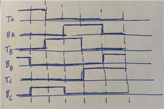
Hi all, my aim is to control a driver of a brushless motor by using 6 pins that come directly from 6 pins of my microcontroller (MSP432P401R), where 3 of them act as normal GPIO and represent the lower transistors (BA, BB, BC) and the other pins have the special function of PWM (TA,TB,TC) and share the same timer and port as well (P2.4, P2.5 and P2.6) respectively. The program is based on a FSM of 6 states and in each state there are 2 pins that stay HIGH and the rest stay LOW as it could be seen in the image above. The sequence is the one that appears in the image and when it arrives to the 6th state it starts over going to the 1rst state and so on. To sum up, TA, TB and TC are controlled using PWM and duty cycle is applied on them to take control of the speed of the motor and BA,BB and BC are normal GPIOs that could be HIGH or LOW depending on the state. My main problem is that I don't know how to switch between TA, TB and TC by applying PWM on one pin and disabling the PWM applied on another pin in the state before, like for example what happens then you reach the 3rd state and you should stop applying PWM to TA and start applying it on TB (hope it's clear). The code I wrote for this is the following one, but I know it has problems and if someone could help me understand what should I do and how to do it in a properly way, I would be really grateful! 

Code:

#include "msp.h"

#define PWM 0x70 // 0111 0000
#define GPIO 0xE0 // 1110 0000
uint8_t estado = 0;

void inicializaciones(void){
/* TA: P2.4; TB: P2.5; TC: P2.6
* BA: P3.5; BB: P3.6; BC: P3.7
*/
// Pins Transistors HIGH (PWM)
P2->SEL0 |= PWM; // Configuramos los pines P2.4 (TA0.1), P2.5 (TA0.2) y P2.6 (TA0.3) 
P2->SEL1 &= ~PWM;
P2->DIR |= PWM; // Para poner TA0.1, TA0.2 y TA0.3 

// Pins Transistors LOW (GPIO)
P3->SEL0 &= ~GPIO;
P3->SEL1 &= ~GPIO;
P3->DIR |= GPIO; // output
}

void TimerA0(void){ // Timer para controlar los 3 pines PWM
TIMER_A0->CCTL[0] = TIMER_A_CCTLN_CCIE; // TACCR0 interrupt enabled
TIMER_A0->CCR[0] = 32767; // Periodo del PWM
TIMER_A0->CTL = TIMER_A_CTL_TASSEL_1 | TIMER_A_CTL_MC__UP; // Reloj ACLK (ACLK = TACLK = 32768H), Up Mode
}

void main(void)
{
WDT_A->CTL = WDT_A_CTL_PW | WDT_A_CTL_HOLD; // stop watchdog timer
inicializaciones();
__enable_irq(); // Enable global interrupt
TimerA0();

while(1){
switch(estado){
case 0: { // TA y BB HIGH
TIMER_A0->CCTL[1] = TIMER_A_CCTLN_OUTMOD_3 |TIMER_A_CCTLN_CCIE; // TACCR1 interrupt enabled; ModoCCR1: Set/Reset
P3->OUT |= (GPIO & ~(BIT7 | BIT5)); // 0100 0000, P3.6 (BB) HIGH
estado++;
}
case 1: { // TA y BC HIGH
P3->OUT |= (GPIO & ~(BIT6 | BIT5)); // 1000 0000, P3.7 (BC) HIGH
estado++;
}
case 2: { // TB y BC HIGH
TIMER_A0->CCTL[2] = TIMER_A_CCTLN_OUTMOD_3 |TIMER_A_CCTLN_CCIE; // TACCR2 interrupt enabled; ModoCCR1: Set/Reset
estado++;
}
case 3: { // BA y TB HIGH
P3->OUT |= (GPIO & ~(BIT7 | BIT6)); // 0010 0000, P3.5 (BA) HIGH
estado++;
}
case 4: { // BA y TC HIGH
TIMER_A0->CCTL[3] = TIMER_A_CCTLN_OUTMOD_3 |TIMER_A_CCTLN_CCIE; // TACCR3 interrupt enabled; ModoCCR1: Set/Reset
estado++;
}
case 5: { // BB y TC HIGH
P3->OUT |= (GPIO & ~(BIT7 | BIT5)); // 0100 0000, P3.6 (BB)  HIGH
estado = 0;
}
}
}
}

void TA0_N_IRQHandler(void)
{
if(TIMER_A0->CCTL[1]&TIMER_A_CCTLN_CCIFG)
{
TIMER_A0->CCTL[1] &= ~TIMER_A_CCTLN_CCIFG;
TIMER_A0->CCR[1] = 8191; // f(ACLK)/4 = 8192Hz
}
if(TIMER_A0->CCTL[2]&TIMER_A_CCTLN_CCIFG)
{
TIMER_A0->CCTL[2] &= ~TIMER_A_CCTLN_CCIFG;
TIMER_A0->CCR[1] = 0; // Reset TA0.1
TIMER_A0->CCR[2] = 8191; // f(ACLK)/4 = 8192Hz
}
if(TIMER_A0->CCTL[3]&TIMER_A_CCTLN_CCIFG)
{
TIMER_A0->CCTL[3] &= ~TIMER_A_CCTLN_CCIFG;
TIMER_A0->CCR[2] = 0; // Reset TA0.2
TIMER_A0->CCR[3] = 8191; // f(ACLK)/4 = 8192Hz
}
if(TIMER_A0->CTL&TIMER_A_CTL_IFG)
{
// Clear timer overflow flag
TIMER_A0->CTL &= ~TIMER_A_CTL_IFG;
}
}

  • Hi Alex,

    I'm not an expert when it comes to driving a brushless motor so I have reached out to our motor control team for help.

  • Hi Alex,

    You are on the right track for doing motor control using PWMs, but these video should help you further your understanding:

    Trapezoidal Control: https://www.youtube.com/watch?v=xIORHY8Ii90

    Comparison of Commutation Methods: https://www.youtube.com/watch?v=InzXA7mWBWE

    For your application, I am assuming you are looking for trapezoidal control, which involves PWM'ing the phases in a 6-state commutation table. I am not sure what you will be using for your gate driver, but assuming you are using a gate driver to control 6 external MOSFETS (one HS + LS for the three phases), you will need to ensure that you follow the commutation methods as described in trapezoidal control to PWM the HS + LS signals for the 3 phases accordingly. 

    The three phases will either be:

    1) High side on (HS = PWM, LS = !PWM or low)

    2) Low side on (HS = low, LS = on)

    3) Floating (HS = LS = Hi-Z)

    I am not very familiar with the MSP432P401R, but we do have a MSP430 software example for 6x PWM trapezoidal control in this reference design.

    In order to PWM, set high, set low, or Hi-Z each gate output, the code uses these functions, which you could port over to the MSP432P401R:

    void A_PWM(void)
    
    {
    	P6SEL0 |= BIT0;
    	P6SEL0 |= BIT1;
    
    }
    
    
    void B_PWM(void)
    
    {
    	P6SEL0 |= BIT2;
    	P6SEL0 |= BIT3;
    
    }
    
    void C_PWM(void)
    
    {
    	P6SEL0 |= BIT4;
    	P6SEL0 |= BIT5;
    
    }
    
    void A_LOW(void)
    {
    	P6SEL0 &= ~BIT0;
    	P6OUT &= ~BIT0;
    	P6SEL0 &= ~BIT1;
    	P6OUT |= BIT1;
    }
    
    void B_LOW(void)
    {
    	P6SEL0 &= ~BIT2;
    	P6OUT &= ~BIT2;
    	P6SEL0 &= ~BIT3;
    	P6OUT |= BIT3;
    }
    
    void C_LOW(void)
    {
    	P6SEL0 &= ~BIT4;
    	P6OUT &= ~BIT4;
    	P6SEL0 &= ~BIT5;
    	P6OUT |= BIT5;
    }
    
    void A_Z(void)
    {
    	P6SEL0 &= ~BIT0;
    	P6OUT &= ~BIT0;
    	P6SEL0 &= ~BIT1;
    	P6OUT &= ~BIT1;
    }
    
    void B_Z(void)
    {
    	P6SEL0 &= ~BIT2;
    	P6OUT &= ~BIT2;
    	P6SEL0 &= ~BIT3;
    	P6OUT &= ~BIT3;
    }
    
    void C_Z(void)
    {
    	P6SEL0 &= ~BIT4;
    	P6OUT &= ~BIT4;
    	P6SEL0 &= ~BIT5;
    	P6OUT &= ~BIT5;
    }
    
    void A_HIGH(void)
    {
        P6SEL0 &= ~BIT0;
        P6OUT |= BIT0;
        P6SEL0 &= ~BIT1;
        P6OUT &= ~BIT1;
    }
    
    void B_HIGH(void)
    {
        P6SEL0 &= ~BIT2;
        P6OUT |= BIT2;
        P6SEL0 &= ~BIT3;
        P6OUT &= ~BIT3;
    }
    
    void C_HIGH(void)
    {
        P6SEL0 &= ~BIT4;
        P6OUT |= BIT4;
        P6SEL0 &= ~BIT5;
        P6OUT &= ~BIT5;
    }

  • About what you said I have some problems understanding the way on how to detect the zero-crossing. I've fixed my problems with creating PWM and achieving what's in the image I posted, but I still feel kind of lost when it comes to determine the BEMF by knowing the zero-crossing between states, as I don't find any code example to understand how to implement it into my case. Perhaps the clue is on what you have said, but unfortunately I don't get it and I also don't see why you are creating all that amount of functions

  • Hi Alex,

    When you commutate the motor with just the PWMs, this is called open loop commutation and it is difficult to spin the motor unless if the rotor position is known. To detect the position, you can use Hall sensors (sensored trapezoidal) for digital feedback or you can calculate the BEMF zero-crossings of the floating phases to change to the next commuation state (sensorless trapezoidal). These methods are called closed-loop commutation. 

    There are many ways to determine the BEMF zero crossing during commutation. You can use comparators to measure VCC/2 on the floating phases, feed the BEMF to ADCs on the MCU and integrate the floating phase BEMF and compare it to a known threshold, or you can measure the phase voltages and currents through ADCs and use a first-order differential equation to calculate the BEMF from the equivalent circuit. 

    Check out the BOOSTXL-DRV832x firmware for the MSP430F5529. We have sensored and sensorless code available in that package. The sensorless code using BEMF integration to estimate the BEMF of the floating phases. We also have the DRV832XX EVM Sensorless Software User's Guide which describes in detail how to calculate the BEMF using the integration technique. 

  • First of all, thanks for all your help. It's really helpful, but I have one last question regarding the firmware for the file for MSP430F5529 and is that I don't know how to find what could be useful for me in this file, so what should I look for and how could I get the software examples? As it's the first time I open such a file like this and I feel somehow lost on where to find the examples like the ones that appear in the Resource Explorer of TI..Thanks in advanced!!

  • Hi Alex,

    After you download the FW for the BOOSTXL-DRV8323RS, you'll need to open and import the project in CCS. Use page 9 of the BOOSTXL-DRV8323Rx EVM User's Guide to show how to import the firmware into Code Composer Studio. Keep in mind, this firmware is for use for use with the BOOSTXL-DRV8323RS Gate Driver + MSP430F5529 LaunchPad, so it's a full sensorless trapezoidal solution that is meant to just be plug-and-play so you can spin a motor quickly with a GUI.

    There is a lot of code you can ignore since a lot of it is for the GUI. If you open global.c and ISR.c, there are functions that record the BEMF from the ADC pins of the phase voltages in hardware and uses those values to calculate the total BEMF and compare it to the center tap voltage (VCC/2). 

    Bear in mind, the least difficult way to use the BEMF and compare it to the center tap is to use a comparator to measure the BEMF. When you try to estimate it by doing more advanced calculations, it becomes a lot more difficult to code the solution. Hall sensors will be the simplest method to determine the position of the motor.

    Here is a great video that can showcase how to commutate the motor using sensored vs. sensorless commutation (go to about 18 minutes): training.ti.com/demystifying-bldc-motor-commutation-trap-sine-foc