This thread has been locked.
If you have a related question, please click the "Ask a related question" button in the top right corner. The newly created question will be automatically linked to this question.
Background:
I have dedicated UART6 (RX PP0) on my TM4C129 to read serial data from another sensor. In terms of the data being received on the TM4C, the sensor sends out (n) frames, each 32 bytes in width, every 7ms. Baud on both sides is 115200.
Objective:
Speed is critical in this case, as the TM4C is responsible for performing other tasks, such as reading encoders and limit switches.
For this reason, I was thinking of taking my interrupt driven approach (see below), and trying to see if I can leverage DMA to basically create a pipe from the UART RX peripheral memory, into my own locally created buffer in SW.
Progress:
I have adapted the basic uart_echo example, but obviously changed things around, so that the data received is from the sensor, opposed to manual input from the user. I then print out the data on UART0 as it is coming in on UART6, and can view it in the serial console (RealTerm).
Question:
After reading up on DMA, and looking over the udma_demo example, I think this might be the best approach. However, I am struggling to adapt my existing code to use it. For example, I see plenty of code out there which sends data over UART TX, facilitated by DMA. But I don't see many examples of having DMA simply receive data from UART RX.
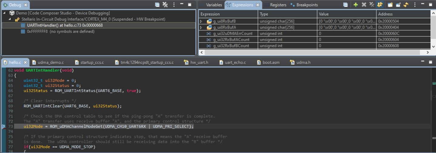
Note that udma_demo does something similar to what I want, but I can't seem to connect the dots. For example, one desirable trait of that sample application is that it has set DMA to use a sort of ping-pong approach. I read the docs in TivaWare, and think this would certainly work for my application in the sense that, while I am collecting those 32 bytes of data over the UART, I could be parsing the previously collected frame (32 bytes), and act accordingly, by the time the next 32 byte chunk comes along.
So I guess that's a long way of asking, is my thought process on how DMA can interact with UART RX valid (peripheral pipe idea mentioned above). And if so, what would be the best approach moving forward. Is there any other example within TivaWare that you can think of, which may help in this case?
Thanks!
Code for reference:
#include <stdint.h> #include <stdbool.h> #include "inc/hw_ints.h" #include "inc/hw_memmap.h" #include "driverlib/debug.h" #include "driverlib/gpio.h" #include "driverlib/interrupt.h" #include "driverlib/pin_map.h" #include "driverlib/rom.h" #include "driverlib/rom_map.h" #include "driverlib/sysctl.h" #include "driverlib/uart.h" uint32_t g_ui32SysClock; #ifdef DEBUG void __error__(char *pcFilename, uint32_t ui32Line) { } #endif void UARTIntHandler(void) { uint32_t ui32Status; ui32Status = ROM_UARTIntStatus(UART6_BASE, true); /* Clear interrupts */ ROM_UARTIntClear(UART6_BASE, ui32Status); /* Read data */ while(ROM_UARTCharsAvail(UART6_BASE)) { /* Should move to blocking charGet() */ ROM_UARTCharPutNonBlocking(UART0_BASE, ROM_UARTCharGetNonBlocking(UART6_BASE)); /* Toggle LED for testing */ GPIOPinWrite(GPIO_PORTN_BASE, GPIO_PIN_0, GPIO_PIN_0); SysCtlDelay(g_ui32SysClock / (1000 * 3)); GPIOPinWrite(GPIO_PORTN_BASE, GPIO_PIN_0, 0); } } int main(void) { /* 120Mhz */ g_ui32SysClock = MAP_SysCtlClockFreqSet((SYSCTL_XTAL_25MHZ | SYSCTL_OSC_MAIN | SYSCTL_USE_PLL | SYSCTL_CFG_VCO_480), 120000000); /* LED */ ROM_SysCtlPeripheralEnable(SYSCTL_PERIPH_GPION); ROM_GPIOPinTypeGPIOOutput(GPIO_PORTN_BASE, GPIO_PIN_0); /* UART 6 */ ROM_SysCtlPeripheralEnable(SYSCTL_PERIPH_UART6); ROM_SysCtlPeripheralEnable(SYSCTL_PERIPH_GPIOP); /* UART 0 */ ROM_SysCtlPeripheralEnable(SYSCTL_PERIPH_UART0); ROM_SysCtlPeripheralEnable(SYSCTL_PERIPH_GPIOA); ROM_IntMasterEnable(); /* Configure As UART 6 on PP0/1 */ GPIOPinConfigure(GPIO_PP0_U6RX); GPIOPinConfigure(GPIO_PP1_U6TX); ROM_GPIOPinTypeUART(GPIO_PORTP_BASE, GPIO_PIN_0 | GPIO_PIN_1); /* Configure As UART 1 on PA0/1 */ GPIOPinConfigure(GPIO_PA0_U0RX); GPIOPinConfigure(GPIO_PA1_U0TX); ROM_GPIOPinTypeUART(GPIO_PORTA_BASE, GPIO_PIN_0 | GPIO_PIN_1); /* 115200 8-N-1 */ ROM_UARTConfigSetExpClk(UART6_BASE, g_ui32SysClock, 115200, (UART_CONFIG_WLEN_8 | UART_CONFIG_STOP_ONE | UART_CONFIG_PAR_NONE)); ROM_UARTConfigSetExpClk(UART0_BASE, g_ui32SysClock, 115200, (UART_CONFIG_WLEN_8 | UART_CONFIG_STOP_ONE | UART_CONFIG_PAR_NONE)); /* Enable ISR */ ROM_IntEnable(INT_UART6); ROM_IntEnable(INT_UART0); ROM_UARTIntEnable(UART6_BASE, UART_INT_RX | UART_INT_RT); while(1){} }
In this case, using uDMA for UART RX makes good sense. You do not see examples of using uDMA for UART RX because often times the number of characters to receive is unknown. uDMA does not work well in that case. In your case, with a continuous stream of characters grouped in blocks of 32, using uDMA in ping-pong mode makes perfect sense. The only issue I see is synchronizing so that you don't start receiving in the middle of the 32 character string.
Hi Bob,
Thanks for the feedback!
After making sure I had UART working as expected, I moved on to pursue the implementation mentioned above. I basically used udma_demo, in conjunction with the DMA section in the DriverLib documentation. Specifically focusing on section 31.2.1, which list the general steps for setting up DMA.
I've attached the code for reference, and I think I'm close, but I may have missed a step.
I can see the UART ISR getting called, but my DMA buffers are not getting filled.
To make things a bit easier for debugger, I have isolated my UART/DMA configuration within configDmaWithUart().
At a first glance, does anything look out of place in that function below. Or any red flags that jump out which may contribute to the issue I am seeing?
Thanks!
Code For Reference:
#include <stdint.h> #include <string.h> #include <stdbool.h> #include "inc/hw_ints.h" #include "inc/hw_memmap.h" #include "inc/hw_uart.h" #include "driverlib/debug.h" #include "driverlib/gpio.h" #include "driverlib/interrupt.h" #include "driverlib/pin_map.h" #include "driverlib/rom.h" #include "driverlib/rom_map.h" #include "driverlib/sysctl.h" #include "driverlib/uart.h" #include "driverlib/udma.h" uint32_t g_ui32SysClock; #if defined(ewarm) #pragma data_alignment=1024 uint8_t pui8ControlTable[1024]; #elif defined(ccs) #pragma DATA_ALIGN(pui8ControlTable, 1024) uint8_t pui8ControlTable[1024]; #else uint8_t pui8ControlTable[1024] __attribute__ ((aligned(1024))); #endif #ifdef DEBUG void __error__(char *pcFilename, uint32_t ui32Line) { } #endif #define UART_RXBUF_SIZE 256 static uint32_t g_ui32RxBufACount = 0; static uint32_t g_ui32RxBufBCount = 0; static uint32_t g_ui32uDMAErrCount = 0; static uint8_t g_ui8RxBufA[UART_RXBUF_SIZE]= {0}; static uint8_t g_ui8RxBufB[UART_RXBUF_SIZE] = {0}; static void configDmaWithUart(void); void uDMAErrorHandler(void) { uint32_t ui32Status; /* Check for uDMA error bit */ ui32Status = ROM_uDMAErrorStatusGet(); /* If there is a uDMA error, then clear the error and increment the error counter */ if(ui32Status) { ROM_uDMAErrorStatusClear(); g_ui32uDMAErrCount++; } } void UARTIntHandler(void) { uint32_t ui32Mode = 0; uint32_t ui32Status = 0; ui32Status = ROM_UARTIntStatus(UART6_BASE, true); /* Clear interrupts */ ROM_UARTIntClear(UART6_BASE, ui32Status); /* Check the DMA control table to see if the ping-pong "A" transfer is complete. The "A" transfer uses receive buffer "A", and the primary control structure */ ui32Mode = ROM_uDMAChannelModeGet(UDMA_CH10_UART6RX | UDMA_PRI_SELECT); /* If the primary control structure indicates stop, that means the "A" receive buffer is done. The uDMA controller should still be receiving data into the "B" buffer */ if(ui32Mode == UDMA_MODE_STOP) { /* Increment a counter to indicate data was received into buffer A */ g_ui32RxBufACount++; /* Set up the next transfer for the "A" buffer, using the primary control structure. When the ongoing receive into the "B" buffer is done, the uDMA controller will switch */ ROM_uDMAChannelTransferSet(UDMA_CH10_UART6RX | UDMA_PRI_SELECT, UDMA_MODE_PINGPONG, (void *)(UART6_BASE + UART_O_DR), g_ui8RxBufA, sizeof(g_ui8RxBufA)); } /* Check the DMA control table to see if the ping-pong "B" transfer is complete. The "B" transfer uses receive buffer "B", and the alternate control structure */ ui32Mode = ROM_uDMAChannelModeGet(UDMA_CH10_UART6RX | UDMA_ALT_SELECT); /* If the alternate control structure indicates stop, that means the "B" receive buffer is done. The uDMA controller should still be receiving data into the "A" buffer */ if(ui32Mode == UDMA_MODE_STOP) { /* Increment a counter to indicate data was received into buffer A */ g_ui32RxBufBCount++; /* Set up the next transfer for the "B" buffer, using the alternate control structure. When the ongoing receive into the "A" buffer is done, the uDMA controller will switch */ ROM_uDMAChannelTransferSet(UDMA_CH10_UART6RX | UDMA_ALT_SELECT, UDMA_MODE_PINGPONG, (void *)(UART6_BASE + UART_O_DR), g_ui8RxBufB, sizeof(g_ui8RxBufB)); } /* Toggle LED for testing */ GPIOPinWrite(GPIO_PORTN_BASE, GPIO_PIN_0, GPIO_PIN_0); SysCtlDelay(g_ui32SysClock / (1000 * 3)); GPIOPinWrite(GPIO_PORTN_BASE, GPIO_PIN_0, 0); } static void configDmaWithUart(void) { /* Enable DMA peripheral */ ROM_SysCtlPeripheralEnable(SYSCTL_PERIPH_UDMA); ROM_SysCtlPeripheralSleepEnable(SYSCTL_PERIPH_UDMA); /* Enable UART 6 peripheral */ ROM_SysCtlPeripheralEnable(SYSCTL_PERIPH_UART6); ROM_SysCtlPeripheralEnable(SYSCTL_PERIPH_GPIOP); ROM_SysCtlPeripheralSleepEnable(SYSCTL_PERIPH_UART6); /* Configure As UART 6 on PP0/1 */ GPIOPinConfigure(GPIO_PP0_U6RX); GPIOPinConfigure(GPIO_PP1_U6TX); ROM_GPIOPinTypeUART(GPIO_PORTP_BASE, GPIO_PIN_0 | GPIO_PIN_1); /* UART 6 @ 115200 8-N-1 */ ROM_UARTConfigSetExpClk(UART6_BASE, g_ui32SysClock, 115200, (UART_CONFIG_WLEN_8 | UART_CONFIG_STOP_ONE | UART_CONFIG_PAR_NONE)); /* Not sure about TX, but I know RX will have 4 byte threshold */ ROM_UARTFIFOLevelSet(UART6_BASE, UART_FIFO_TX4_8, UART_FIFO_RX4_8); /* Enable the UART for operation, and enable the uDMA interface for RX only */ ROM_UARTEnable(UART6_BASE); ROM_UARTDMAEnable(UART6_BASE, UART_DMA_RX); /* Enable DMA interrupts */ ROM_IntEnable(INT_UDMAERR); /* Enable DMA */ ROM_uDMAEnable(); /* Point at the control table to use for channel control structures */ ROM_uDMAControlBaseSet(pui8ControlTable); /* Put the attributes in a known state */ ROM_uDMAChannelAttributeDisable(UDMA_CH10_UART6RX, UDMA_ATTR_ALTSELECT | UDMA_ATTR_USEBURST | UDMA_ATTR_HIGH_PRIORITY | UDMA_ATTR_REQMASK); /* Enable DMA attributes for UART6 RX (buffer A). In this case, the transfer data size is 8 bits, the source address does not increment since it will be reading from a register. The destination address increment is byte 8-bit bytes. The arbitration size is set to 4 to match the RX FIFO trigger threshold */ ROM_uDMAChannelControlSet(UDMA_CH10_UART6RX | UDMA_PRI_SELECT, UDMA_SIZE_8 | UDMA_SRC_INC_NONE | UDMA_DST_INC_8 | UDMA_ARB_4); /* Enable DMA attributes for UART6 RX (buffer B). Setting this an the alternate control structure B. Configuration is the same as above */ ROM_uDMAChannelControlSet(UDMA_CH10_UART6RX | UDMA_ALT_SELECT, UDMA_SIZE_8 | UDMA_SRC_INC_NONE | UDMA_DST_INC_8 | UDMA_ARB_4); /* Set transfer parameters for the primary RX control structure in ping-pong mode. The transfer source will be the UART RX data register, and the destination will be buffer A */ ROM_uDMAChannelTransferSet(UDMA_CH10_UART6RX | UDMA_PRI_SELECT, UDMA_MODE_PINGPONG, (void *)(UART6_BASE + UART_O_DR), g_ui8RxBufA, sizeof(g_ui8RxBufA)); /* Same logic applies above, except we are now setting up the alternative buffer (B) */ ROM_uDMAChannelTransferSet(UDMA_CH10_UART6RX | UDMA_ALT_SELECT, UDMA_MODE_PINGPONG, (void *)(UART6_BASE + UART_O_DR), g_ui8RxBufB, sizeof(g_ui8RxBufB)); /* The DMA should now be configured for UART RX in ping-ping mode, with both primary and secondary buffers pointing to the UART data register */ ROM_uDMAChannelEnable(UDMA_CH10_UART6RX); /* Enable DMA for UART RX. Stop DMA if there's a UART error */ ROM_UARTDMAEnable(UART6_BASE, UART_DMA_RX | UART_DMA_ERR_RXSTOP); /* Enable UART */ ROM_IntEnable(INT_UART6); ROM_UARTIntEnable(UART6_BASE, UART_INT_RX | UART_INT_RT); } int main(void) { /* 120Mhz */ g_ui32SysClock = MAP_SysCtlClockFreqSet((SYSCTL_XTAL_25MHZ | SYSCTL_OSC_MAIN | SYSCTL_USE_PLL | SYSCTL_CFG_VCO_480), 120000000); /* LED */ ROM_SysCtlPeripheralEnable(SYSCTL_PERIPH_GPION); ROM_SysCtlPeripheralEnable(SYSCTL_PERIPH_GPIOA); ROM_GPIOPinTypeGPIOOutput(GPIO_PORTN_BASE, GPIO_PIN_0); /* Enable UART 0 peripheral */ ROM_SysCtlPeripheralEnable(SYSCTL_PERIPH_UART0); ROM_SysCtlPeripheralSleepEnable(SYSCTL_PERIPH_UART0); /* Enable processor interrupts */ ROM_IntMasterEnable(); /* Configure As UART 1 on PA0/1 */ GPIOPinConfigure(GPIO_PA0_U0RX); GPIOPinConfigure(GPIO_PA1_U0TX); ROM_GPIOPinTypeUART(GPIO_PORTA_BASE, GPIO_PIN_0 | GPIO_PIN_1); /* 115200 8-N-1 */ ROM_UARTConfigSetExpClk(UART0_BASE, g_ui32SysClock, 115200, (UART_CONFIG_WLEN_8 | UART_CONFIG_STOP_ONE | UART_CONFIG_PAR_NONE)); /* Enable ISR */ ROM_IntEnable(INT_UART0); configDmaWithUart(); memset(g_ui8RxBufA, 0x00, sizeof(g_ui8RxBufA)); memset(g_ui8RxBufB, 0x00, sizeof(g_ui8RxBufB)); /* Spin */ while(1) { SysCtlDelay(g_ui32SysClock / 20 / 3); } }
I will take a closer look at the code when I am back in the office on Monday. I have attached an ADC example that uses uDMA in ping-pong mode. It might help.
Thank you Bob Crosby, your example certainly helped.
I worked on this a bit over the weekend, and have it somewhat working. I also adapted a few ideas from that ADC example you attached, to help with debugging.
What I found so far is that, if I use UART RX 0 or 1, it works, in the sense that I can see the DMA buffers filling. I need to verify the data, but it's certainly working to some extent.
Another topic I was struggling with is the relation UART has with DMA, specifically in terms of interrupts. I did poke around TI's documentation to see if there was any app notes around DMA, but couldn't find any. Basically in my code I am registering for a couple different interrupts, but I'm doing this blindly, as I don't necessarily know which ones are needed. For example:
/* The DMA should now be configured for UART RX in ping-ping mode, with both primary and secondary buffers pointing to the UART data register */ ROM_uDMAChannelEnable(UDMA_CHANNEL_UART1RX); /* Enable DMA for UART RX. Stop DMA if there's a UART error */ ROM_UARTDMAEnable(UART1_BASE, UART_DMA_RX | UART_DMA_ERR_RXSTOP); /* Enable UART */ ROM_IntEnable(INT_UART1); ROM_UARTIntEnable(UART1_BASE, UART_INT_RX | UART_INT_RT); ROM_UARTIntEnable(UART1_BASE, UART_INT_DMATX | UART_INT_DMARX);
"UART RX interrupt is received first, then that lets DMA do X, so you are required to register for X ISR if you want the DMA buffer to fill (n) bytes."
udma.h
, they have 31 default channel numbers, for example UDMA_CHANNEL_XXXX
. The UART I was using for UART 6 RX did not map to any of those. So I switched to one that was mapped (UDMA_CHANNEL_UART1RX
), and then everything started to work. UDMA_CH10_UART6RX
, but maybe that's not how the API was meant to be used, or they are generic definitions, and my particular launchpad does not support that DMA channel? Anyway, just curious what you think.Thanks again for the help!
To use UART6 with uDMA you need to all an additional function, uDMAChannelAssign(). The 32 uDMA channels can have up to 9 different connections. For compatibility, if the channel is mapped to group 0, (such as is the case with UART1RX on channel 8) you do not need to call the uDMAChannelAssign() function.
uDMAChannelAssign(UDMA_CH10_UART6RX); uDMAChannelAssign(UDMA_CH11_UART6TX); uDMAChannelEnable(UDMA_CH10_UART6RX); uDMAChannelEnable(UDMA_CH11_UART6TX);
Also related to #1, but since these 32 bytes are received over UART, should I continue to use the UART FIFO, or does that add a level of complexity. I'm guessing by adding the FIFO route, the ISR will trigger at a given fill level, opposed to each character, but I'm not sure how that will have an impact on DMA, and how it accumulates the data from the UART RX data buffer?
In this case I don't think it will make much difference. If you use the FIFO the UART will make a burst uDMA request. Other DMA requests are ignored until the burst completes. (The CPU will still get any bus cycle it wants, interrupting the burst if needed.) A burst request is slightly more efficient from a DMA perspective. It does increase the latency of other DMA requests, but the use of the FIFO allows for more latency if only using UARTS for DMA. If you are only using one channel of uDMA, the difference is totally insignificant. Here is some information from the datasheet.