This thread has been locked.

If you have a related question, please click the "Ask a related question" button in the top right corner. The newly created question will be automatically linked to this question.

EK-TM4C1294XL: How to detect whether falling or rising edge is arrived in the ISR if the gpio PD0 is configured as an Edge Triggered mode?

Part Number: EK-TM4C1294XL

Hello

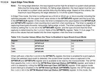
I'm working with the TM4C1294XL evaluation board. I'm connecting the waveform generator to the PD0 of the board. So basically my task is to calculate the turn-on time of the received duty cycle. For doing so, PD0 is configured as follows

	void GPIOInit()
	{

		//
		// Enable the GPIOD peripheral
		//
		SysCtlPeripheralEnable(SYSCTL_PERIPH_GPIOD);
		
		//
		// Wait for the GPIOD module to be ready.
		//
		while(!SysCtlPeripheralReady(SYSCTL_PERIPH_GPIOD))
		{
		}
		
		//
		// Register the port-level interrupt handler. This handler is the first
		// level interrupt handler for all the pin interrupts.
		//
		GPIOIntRegister(GPIO_PORTD_BASE, GPIOD_Handler);
		
		//
		// Initialize the GPIO pin configuration.
		//
		// Set pins 0 as input, SW controlled.
		//
		GPIOPinTypeGPIOInput(GPIO_PORTD_BASE, GPIO_PIN_0);
		
		//
		// Make pins 0 rising edge triggered interrupts.
		//
		GPIOIntTypeSet(GPIO_PORTD_BASE, GPIO_PIN_0, GPIO_BOTH_EDGES);
		GPIOPinWrite(GPIO_PORTD_BASE, GPIO_PIN_0,0);
		
		i32Val = GPIOPinRead(GPIO_PORTD_BASE, GPIO_PIN_0);
		
		UARTprintf("\n\nInitial value of PD0 = '%d'",i32Val);
		
		//
		// Enable the pin interrupts.
		//
		GPIOIntEnable(GPIO_PORTD_BASE, GPIO_INT_PIN_0);
		
	}

Now the point is, in the ISR I want to detect when exactly the rising edge or falling edge arrives so that I can capture the timer counter value exactly when the falling edge arrives. Initially, I thought that if zero received at the pin PD0 then the falling edge is received and if one is received then it should be the rising edge but I'm not sure about this.The which I have written is as follows,

void GPIOD_Handler(void)
{
		uint32_t status;
	
		status = GPIOIntStatus(GPIO_PORTD_BASE,true);
    //
    // Clear the interrupt.
    //
    GPIOIntClear(GPIO_PORTD_BASE, status);
	
		check_edge = GPIOPinRead(GPIO_PORTD_BASE, GPIO_PIN_0);
	
		if(check_edge == 0) //positive edge detected
		{	
			UARTprintf("\n\nPositive edge DETECTED!!");
			i32Val = GPIOPinRead(GPIO_PORTD_BASE, GPIO_PIN_0);
		
			UARTprintf("\nPositive Edge value of PD0 = '%d'",i32Val);
		}
		
		else if(check_edge == 1) //negative edge detected
		{
			flag = true;
			UARTprintf("\n\nNegative edge DETECTED!!");
			i32Val = GPIOPinRead(GPIO_PORTD_BASE, GPIO_PIN_0);
		
			UARTprintf("\nNegative Edge value of PD0 = '%d'",i32Val);
		}
			GPIOIntDisable(GPIO_PORTD_BASE, GPIO_INT_PIN_0);
}

Also, I'm attaching the output where some random 0 snd 1's are received!.

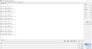
So I wanted to be sure in the ISR that whether falling or rising edge received.

Any help or suggestion will be really appreciated!

Regards,

Omkar Dixit

  • Hi,

      I think your choice of using GPIO to measure time of an input is wrong. You should use the timer module in Edge Time mode instead. Please refer to timer module Input Edge-Time mode for detail. 

    There is an example in C:\ti\TivaWare_C_Series-2.2.0.295\examples\boards\ek-tm4c1294xl\timer_edge_capture doing duty cycle measurement. I suggest you reference the example. This example uses two timer to measure any duty cycle. But you may be able to use just one timer if your duty cycle is longer than the time it takes the processor to enter interrupt. In another word, in your application, if the duty cycle is long enough you may be able to work with just one timer.  Using GPIO to measure time is not the right solution in my opinion.

    //! <h1>Timer Edge Capture Demo (timer_edge_capture)</h1>
    //!
    //! This example demonstrates how to use two timers to determine the duration
    //! of the high period of an input signal.  The same logic can be applied to
    //! also measure the low period.  The example uses Timer 0 in Split Mode and
    //! the 8-bit prescaler to create two 24-bit wide timers.  There are some
    //! limitations with this method to be aware of.  The limitation on the lower
    //! end is if a signal is too fast to sample with the timers due to the time to
    //! execute code.  The limitation on the upper end is if the signal period is
    //! longer than 139.8 milliseconds at which point the 24-bit timer would
    //! overflow.  That issue can be worked around by using two 32-bit timers which
    //! would allow measuring a signal up to 35.79 seconds long.
    //!
    //! To test this example either input a square wave to PL4 and PL5 with a
    //! signal generator or leverage a second LaunchPad running a TivaWare PWM
    //! project such as pwm_interrupt.
    //!
    //! This example uses the following peripherals and I/O signals.
    //! - GPIO Port L peripheral (for TIMER0 pins)
    //! - T0CCP0 - PL4
    //! - T0CCP1 - PL5
  • Hello Charles

    Thanks for the quick reply. Okay, I will try the method which you have suggested.

    Regards

    Omkar

  • I have tried the example which you have suggested above. In my project, I'm going to use only one pin which will be configured as a timer(PD0). So, I wanted to know can I detect both the edges in the one Timer0AIntHandler ISR if yes then how to do the same??

    I'm trying this for a long time so, any help will be really appreciated!!

  • So, I wanted to know can I detect both the edges in the one Timer0AIntHandler ISR if yes then how to do the same

    To detect both edges just specify both edges like below example. 

    TimerControlEvent(TIMER0_BASE, TIMER_A, TIMER_EVENT_BOTH_EDGES);

    In my project, I'm going to use only one pin which will be configured as a timer(PD0).

    Use two pins is more reliable for measuring any duty cycles and I highly recommend you do with two pins if possible.  If you really just want to use one pin then each time you detect an edge, an interrupt is generated. In the ISR you will need to first read the pin state. If the pin is high then it means you have a rise edge. Save the current timer value (by calling TimerValueGet()) and save to a variable called rise_edge. Next time when you get an interrupt, it must be a falling edge and save the current counter value into a variable called fall_edge. When you take the difference ( fall_edge - rise_edge), it becomes your duty cycle width. 

  • Okay, I will discuss this with my team regarding using two pins instead of using only one. Thank you so much Charles for your as always detailed explanation.

    Regards

    Omkar