This thread has been locked.

If you have a related question, please click the "Ask a related question" button in the top right corner. The newly created question will be automatically linked to this question.

EK-TM4C123GXL: Failing to use I2C

Part Number: EK-TM4C123GXL
Other Parts Discussed in Thread: TM4C123GH6PM, ENERGIA

Hello,

I'm trying to transmit data through I2C. However I can't seem to get it to work.

Using CCS Version 10.3.0.00007 , I replicated the Programming Example under 16.3 of the peripheral user guide, provided by TI, see link:

www.ti.com/.../spmu298e.pdf

I'll attach my code:

#include <stdint.h>
#include <stdbool.h>
#include "inc/hw_ints.h"
#include "inc/hw_memmap.h"
#include "inc/hw_types.h"
#include "driverlib/debug.h"
#include "driverlib/fpu.h"
#include "driverlib/gpio.h"
#include "driverlib/interrupt.h"
#include "driverlib/pin_map.h"
#include "driverlib/rom.h"
#include "driverlib/sysctl.h"
#include "driverlib/timer.h"
#include "driverlib/i2c.h"

//*****************************************************************************
//
// The error routine that is called if the driver library encounters an error.
//
//*****************************************************************************
#ifdef DEBUG
void
__error__(char *pcFilename, uint32_t ui32Line)
{
}
#endif

void ConfigureI2CasMaster()
{
SysCtlPeripheralEnable(SYSCTL_PERIPH_I2C0);

while (!SysCtlPeripheralReady(SYSCTL_PERIPH_I2C0))
{

}

// set bus speed and enable master
I2CMasterInitExpClk(I2C0_BASE, SysCtlClockGet(), true);

I2CMasterSlaveAddrSet(I2C0_BASE, 0x3B, false);

I2CMasterDataPut(I2C0_BASE, 'Q');

I2CMasterControl(I2C0_BASE, I2C_MASTER_CMD_SINGLE_SEND);

while (I2CMasterBusBusy(I2C0_BASE))
{

}

}

void SendI2CData()
{

I2CMasterDataPut(I2C0_BASE, 'Q');

I2CMasterControl(I2C0_BASE, I2C_MASTER_CMD_SINGLE_SEND);

while (I2CMasterBusBusy(I2C0_BASE))
{

}

}

//*****************************************************************************
//
// main
//
//*****************************************************************************

int main(void)
{
// Setup the system clock to run at 40 MHz from PLL with crystal reference
ROM_SysCtlClockSet(SYSCTL_SYSDIV_5 | SYSCTL_USE_PLL | SYSCTL_XTAL_16MHZ |
SYSCTL_OSC_MAIN);

ConfigureI2CasMaster();

// enter the Loop
while (1)
{
SysCtlDelay(10000);
SendI2CData();
}
}

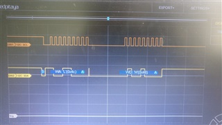
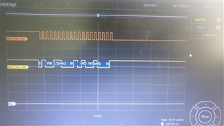
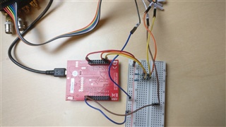
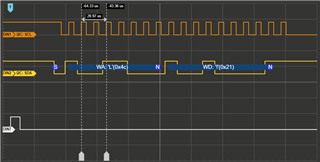
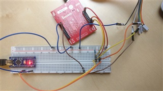
I have a logic analyzer on pin B2 and B3, which are SCL0 and SDA0 on the TM4c123GXL Board.

GND is connected and the logic analyzer is set up properly.  (tested on a different device)

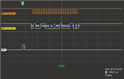
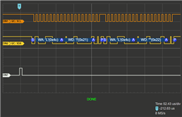
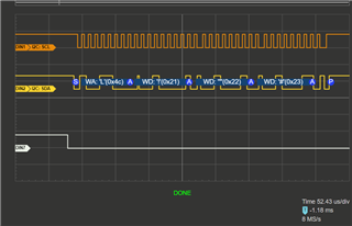
I would expect my code to repeatedly transmit data, however my logic analyzer shows me that absolutely nothing happens.

Is something wrong with my code?

Thank you

  • I have a logic analyzer on pin B2 and B3, which are SCL0 and SDA0 on the TM4c123GXL Board

    In the posted code I can't see any calls to set the B2 and B3 pins to be controlled by the I2C0 peripheral. While Table 10-2. GPIO Pins and Alternate Functions (64LQFP) in the TM4C123GH6PM datasheet shows PB2 and PB3 default to the pin mux for I2C0SCL and I2C0SDA, TivaWare_C_Series-2.2.0.295/examples/peripherals/i2c/master_slave_loopback.c shows the following calls be made to configure B2 and B3 for I2C, as well as the call to SysCtlPeripheralEnable() for the I2C0 peripheral:

        //
        // The I2C0 peripheral must be enabled before use.
        //
        SysCtlPeripheralEnable(SYSCTL_PERIPH_I2C0);
    
        //
        // For this example I2C0 is used with PortB[3:2].  The actual port and
        // pins used may be different on your part, consult the data sheet for
        // more information.  GPIO port B needs to be enabled so these pins can
        // be used.
        // TODO: change this to whichever GPIO port you are using.
        //
        SysCtlPeripheralEnable(SYSCTL_PERIPH_GPIOB);
    
        //
        // Configure the pin muxing for I2C0 functions on port B2 and B3.
        // This step is not necessary if your part does not support pin muxing.
        // TODO: change this to select the port/pin you are using.
        //
        GPIOPinConfigure(GPIO_PB2_I2C0SCL);
        GPIOPinConfigure(GPIO_PB3_I2C0SDA);
    
        //
        // Select the I2C function for these pins.  This function will also
        // configure the GPIO pins pins for I2C operation, setting them to
        // open-drain operation with weak pull-ups.  Consult the data sheet
        // to see which functions are allocated per pin.
        // TODO: change this to select the port/pin you are using.
        //
        GPIOPinTypeI2CSCL(GPIO_PORTB_BASE, GPIO_PIN_2);
        GPIOPinTypeI2C(GPIO_PORTB_BASE, GPIO_PIN_3);
    Can you try adding the above calls from the TivaWare example to your code to see if I2C activity is generated on the pins?

    Also assume that the hardware has pull-up resistors on the SCL and SDA signals.

  • Hi,

      Chester is right that you didn't configure the I2C pins. There are several examples in C:\ti\TivaWare_C_Series-2.2.0.295\examples\peripherals\i2c that you reference as well as a complete CCS project in C:\ti\TivaWare_C_Series-2.2.0.295\examples\boards\ek-tm4c123gxl-boostxl-senshub\humidity_sht21_simple that you can import into CCS and run it right away. 

  • Thank you both!

  • I stumbled upon another thing, which I don't know how to solve:

    I'm trying to send more then one byte of information per transaction.

    Right now I'm able to send one byte (first, the address byte, then the information byte) but I need to send more than that (address, command and two values)

    I tried the following, without success:

    #include <stdint.h>
    #include <stdbool.h>
    #include "inc/hw_i2c.h"
    #include "inc/hw_ints.h"
    #include "inc/hw_memmap.h"
    #include "inc/hw_types.h"
    #include "driverlib/debug.h"
    #include "driverlib/fpu.h"
    #include "driverlib/gpio.h"
    #include "driverlib/interrupt.h"
    #include "driverlib/pin_map.h"
    #include "driverlib/rom.h"
    #include "driverlib/sysctl.h"
    #include "driverlib/timer.h"
    #include "driverlib/i2c.h"
    
    //*****************************************************************************
    //
    // The error routine that is called if the driver library encounters an error.
    //
    //*****************************************************************************
    #ifdef DEBUG
    void
    __error__(char *pcFilename, uint32_t ui32Line)
    {
    }
    #endif
    
    void ConfigureI2CasMaster()
    {
    //
    // enable I2C0 Peripheral
        SysCtlPeripheralEnable(SYSCTL_PERIPH_I2C1);
    
    //
    // wait until it's enabled
        while (!SysCtlPeripheralReady(SYSCTL_PERIPH_I2C1))
        {
        }
    
    //
    // enable GPIO Port B
        SysCtlPeripheralEnable(SYSCTL_PERIPH_GPIOA);
    
    //
    // wait until it's enabled
        while (!SysCtlPeripheralReady(SYSCTL_PERIPH_GPIOA))
        {
        }
    
    //
    // Configure the pin muxing for I2C0 functions on port B2 and B3.
        GPIOPinConfigure(GPIO_PA6_I2C1SCL);
        GPIOPinConfigure(GPIO_PA7_I2C1SDA);
    
    //
    // Select the I2C function for these pins.  This function will also
    // configure the GPIO pins pins for I2C operation, setting them to
    // open-drain operation with weak pull-ups.
        GPIOPinTypeI2CSCL(GPIO_PORTA_BASE, GPIO_PIN_6);
        GPIOPinTypeI2C(GPIO_PORTA_BASE, GPIO_PIN_7);
    
    //
    // set bus speed and enable master
        I2CMasterInitExpClk(I2C1_BASE, SysCtlClockGet(), true);
    
    //
    // set slave address
        I2CMasterSlaveAddrSet(I2C1_BASE, 0x4C, false);
    
    
        SendI2CData();
    }
    
    void SendI2CData()
    {
    
    I2CMasterDataPut(I2C1_BASE, 'H');
    I2CMasterControl(I2C1_BASE, I2C_MASTER_CMD_BURST_SEND_START);
    while (I2CMasterBusBusy(I2C1_BASE))
    {
    }
    
    I2CMasterDataPut(I2C1_BASE, 'E');
    I2CMasterControl(I2C1_BASE, I2C_MASTER_CMD_BURST_SEND_CONT);
    while (I2CMasterBusBusy(I2C1_BASE))
    {
    }
    
    I2CMasterDataPut(I2C1_BASE, 'L');
    I2CMasterControl(I2C1_BASE, I2C_MASTER_CMD_BURST_SEND_CONT);
    while (I2CMasterBusBusy(I2C1_BASE))
    {
    }
    
    I2CMasterDataPut(I2C1_BASE, 'P');
    I2CMasterControl(I2C1_BASE, I2C_MASTER_CMD_BURST_SEND_FINISH);
    while (I2CMasterBusBusy(I2C1_BASE))
    {
    }
    
    // as output, I only see the address, followed by the last byte ('P')
    
    }
    
    //*****************************************************************************
    //
    // main
    //
    //*****************************************************************************
    
    int main(void)
    {
    // Setup the system clock to run at 40 MHz from PLL with crystal reference
    ROM_SysCtlClockSet(SYSCTL_SYSDIV_5 | SYSCTL_USE_PLL | SYSCTL_XTAL_16MHZ |
    SYSCTL_OSC_MAIN);
    
    //
    // the following 6 lines of code set the PF2 Pin high and low once in quick succession
    // I do this to trigger my logic analyzer
    SysCtlPeripheralEnable(SYSCTL_PERIPH_GPIOF);
    while(!SysCtlPeripheralReady(SYSCTL_PERIPH_GPIOF)) {}
    GPIOPinTypeGPIOOutput(GPIO_PORTF_BASE, GPIO_PIN_2);
    
    GPIOPinWrite(GPIO_PORTF_BASE, GPIO_PIN_2, GPIO_PIN_2);
    SysCtlDelay(1000);
    GPIOPinWrite(GPIO_PORTF_BASE, GPIO_PIN_2, 0);
    
    
    ConfigureI2CasMaster();
    
    // enter the Loop
    while (1)
    {
    
    }
    }
    

    I removed SendData from the Loop, now there is only one transmission upon start of the programm. I used PF2 to trigger my logic analyzer. I tried the BURST_MODE command but as stated in the code, it will still only send one byte. Namely, the last one that I put before I end the burst mode.

    I based my code upon the example of Charles. (humidity_sht21_simple) Burst mode is used there in a pretty similar way (I think) but only for receiving. Maybe thats the important difference.

    So, my question is, has someone and idea or can point me in the right direction? I didn't found examples where Burst Mode is used for transmitting and the driver lib documentation does not go into much detail about this.

    Thank you

    Lucas

  • Hello Lucas,

    I am taking over this from Charles but I haven't had a chance to test your code yet, I will try and get back to you tomorrow on this, sorry for the delay.

  • No worries, thank you!

  • Hello Lucas,

    Sorry for the delay here, it took me a bit to figure out some of what is going on. I am not sure this will solve it fully, but lets see how this helps.

    I was able to see the same behavior you did, and after trying a few different methods to send the data, it looked like there wasn't enough delay time involved. The following sequence I thought usually only was needed for our TM4C129x devices, but it definitely improved the performance here. So give that a try and let me know what you see next. If it isn't working, when you look at the scope or LSA, can you indicate if the slave releases the SCL line after the transaction finishes?

    	I2CMasterDataPut(I2C1_BASE, 'H');
    	I2CMasterControl(I2C1_BASE, I2C_MASTER_CMD_BURST_SEND_START);
        while(!I2CMasterBusBusy(I2C1_BASE))
        {
        }
        while(I2CMasterBusBusy(I2C1_BASE))
        {
        }
    
    	I2CMasterDataPut(I2C1_BASE, 'E');
    	I2CMasterControl(I2C1_BASE, I2C_MASTER_CMD_BURST_SEND_CONT);
        while(!I2CMasterBusBusy(I2C1_BASE))
        {
        }
        while(I2CMasterBusBusy(I2C1_BASE))
        {
        }
    
    	I2CMasterDataPut(I2C1_BASE, 'L');
    	I2CMasterControl(I2C1_BASE, I2C_MASTER_CMD_BURST_SEND_CONT);
        while(!I2CMasterBusBusy(I2C1_BASE))
        {
        }
        while(I2CMasterBusBusy(I2C1_BASE))
        {
        }
    
    	I2CMasterDataPut(I2C1_BASE, 'P');
    	I2CMasterControl(I2C1_BASE, I2C_MASTER_CMD_BURST_SEND_FINISH);
        while(!I2CMasterBusBusy(I2C1_BASE))
        {
        }
        while(I2CMasterBusBusy(I2C1_BASE))
        {
        }

  • Hello Ralph,

    thank you for taking the time.

    Unfortunately, this did not resolve the issue, but it produced interesting results.

    First off, sorry for the bad quality. I took the photos from my phone. The computer that the logic analyzer is connected to has no connection to the internet so I'm unable to transfer screenshots. (usb stick does not work for other reasons)

    This first picture shows the outcome of the code you suggested with a slave connected. As you see, the data is acknowledged, but only the address (0x4C in this case) and the first byte 'H' is sent. The SCL line is not released for another at least 200ms, where the scope of my analyzer ends. Till then, nothing else happens.

    I did notice though, that the byte 'H' is the first byte that is to be sent in the code. Until now, it was always the last byte that i put before the _FINISH command that was sent. So in this case I would have expected it to be address and the 'P' byte.

    And without the double  while(!I2CMasterBusBusy(I2C1_BASE)){}  , that will still happen. So that problem is fixed.

    Without a Slave connected

    Second picture shows the same code, but without a slave connected. Data is not acknowledged but SCL line still not released. So, without a slave connected, we have to assume that it's the tm4c123 that keeps SCL low, right?

    Regards

    Lucas

  • Hello Lucas,

    I was not able to replicate the behavior you described without a slave connected. I am wondering if there might be a hardware issue going on here. What is the value of the pull-up resistors you are using for your board? Are the pull-ups still attached to the I2C bus when you disconnect the slave?

    Another point I'd be curious about... I know ultimately you want to use Burst Send, but can you try using I2C_MASTER_CMD_SINGLE_SEND and see if that changes your results at all?

  • Hi Ralph,

    I'm happy to provide some more details.

    First off, what do I want to accomplish?

    I need to send three bytes of information to my slave (a configurable dc/dc converter) 

    These three bytes are a command (what value to configure) and two bytes (high byte and low byte) of the desired value.

    I restructured the code a little bit to make it more straightforward:

    #include <stdint.h>
    #include <stdbool.h>
    #include "inc/hw_i2c.h"
    #include "inc/hw_ints.h"
    #include "inc/hw_memmap.h"
    #include "inc/hw_types.h"
    #include "driverlib/debug.h"
    #include "driverlib/fpu.h"
    #include "driverlib/gpio.h"
    #include "driverlib/interrupt.h"
    #include "driverlib/pin_map.h"
    #include "driverlib/rom.h"
    #include "driverlib/sysctl.h"
    #include "driverlib/timer.h"
    #include "driverlib/i2c.h"
    
    //*****************************************************************************
    //
    // The error routine that is called if the driver library encounters an error.
    //
    //*****************************************************************************
    #ifdef DEBUG
    void
    __error__(char *pcFilename, uint32_t ui32Line)
    {
    }
    #endif
    
    //
    // define the slave address
    #define ADDRESS 0x4C
    
    //
    // define the three bytes that are to be sent
    #define COMMAND  0x21
    #define VALUE_1  0x22
    #define VALUE_2  0x23
    
    //*****************************************************************************
    //
    // main
    //
    //*****************************************************************************
    
    int main(void)
    {
    //
    // Setup the system clock to run at 40 MHz from PLL with crystal reference
        SysCtlClockSet(SYSCTL_SYSDIV_5 | SYSCTL_USE_PLL | SYSCTL_XTAL_16MHZ |
        SYSCTL_OSC_MAIN);
    
    //
    // Enable GPIO Port F and set pin PF2 as an output pin
        SysCtlPeripheralEnable(SYSCTL_PERIPH_GPIOF);
        while (!SysCtlPeripheralReady(SYSCTL_PERIPH_GPIOF))
        {
        }
        GPIOPinTypeGPIOOutput(GPIO_PORTF_BASE, GPIO_PIN_2);
    
    //
    // use PF2 as trigger for the logic analyzer
        GPIOPinWrite(GPIO_PORTF_BASE, GPIO_PIN_2, GPIO_PIN_2);
        SysCtlDelay(100);
        GPIOPinWrite(GPIO_PORTF_BASE, GPIO_PIN_2, 0);
    
    
    //
    // enable I2C1 Peripheral
        SysCtlPeripheralEnable(SYSCTL_PERIPH_I2C1);
    
    //
    // wait until it's enabled
        while (!SysCtlPeripheralReady(SYSCTL_PERIPH_I2C1))
        {
        }
    
    //
    // enable GPIO Port B
        SysCtlPeripheralEnable(SYSCTL_PERIPH_GPIOA);
    
    //
    // wait until it's enabled
        while (!SysCtlPeripheralReady(SYSCTL_PERIPH_GPIOA))
        {
        }
    
    //
    // Configure the pin muxing for I2C1 functions on port A6 and A7.
        GPIOPinConfigure(GPIO_PA6_I2C1SCL);
        GPIOPinConfigure(GPIO_PA7_I2C1SDA);
    
    //
    // Select the I2C function for these pins.  This function will also
    // configure the GPIO pins pins for I2C operation, setting them to
    // open-drain operation with weak pull-ups.
        GPIOPinTypeI2CSCL(GPIO_PORTA_BASE, GPIO_PIN_6);
        GPIOPinTypeI2C(GPIO_PORTA_BASE, GPIO_PIN_7);
    
    //
    // set clock speed and enable master
        I2CMasterInitExpClk(I2C1_BASE, SysCtlClockGet(), false);
    
    //
    // set the slave address
        I2CMasterSlaveAddrSet(I2C1_BASE, ADDRESS, false);
    
    //
    // transfer the COMMAND byte first
        I2CMasterDataPut(I2C1_BASE, COMMAND);
        I2CMasterControl(I2C1_BASE, I2C_MASTER_CMD_BURST_SEND_START);
        while (!I2CMasterBusBusy(I2C1_BASE))
        {
        }
        while (I2CMasterBusBusy(I2C1_BASE))
        {
        }
    
    //
    // transfer the VALUE_1 byte then
        I2CMasterDataPut(I2C1_BASE, VALUE_1);
        I2CMasterControl(I2C1_BASE, I2C_MASTER_CMD_BURST_SEND_CONT);
        while (!I2CMasterBusBusy(I2C1_BASE))
        {
        }
        while (I2CMasterBusBusy(I2C1_BASE))
        {
        }
    
    //
    // transfer the VALUE_2 byte finally
        I2CMasterDataPut(I2C1_BASE, VALUE_2);
        I2CMasterControl(I2C1_BASE, I2C_MASTER_CMD_BURST_SEND_FINISH);
        while (!I2CMasterBusBusy(I2C1_BASE))
        {
        }
        while (I2CMasterBusBusy(I2C1_BASE))
        {
        }
    
    //
    // enter the Loop
        while (1)
        {
        }
    }

    As you can see now, I only try to send three bytes in the same manner as you suggested with your code example.

    Slaveless Setup:

    In this setup there is no slave connected. The brown lines are used to trigger the analyzer. The orange (SCL) and yellow (SDA) lines connect the LaunchPad to my logic analyzer. You can probably see the pullup resistors too. So yes, even without a slave, the pullups are connected. I use 5 kOhm resistors. I also tried 2.8 k and 8.9 k. All produce the same result on my logic analyzer:

    As we see, only one byte (the COMMAND byte 0x21, which is the first byte I want to transmit) is transmitted (apart from the address of course)

    Bytes are obviously not acknowledged. SCL is held low after the transaction (must be the LaunchPad since no other device apart from the logic analyzer is connected)

    Setup with Slave:

    As you can probably see, the slave is an arduino nano. I did this because the actual dcdc converter is embedded on a pretty messy pcb. To make it easier for you to check my setup, I chose to use this. However, I tested the abovementioned code on the arduino AND on the mentioned dcdc converter and got the exact same result:

    You can see the console on the right. The exclamation mark in the console indicates that the COMMAND 0x21 was received by the slave. But again, ONLY the exclamation mark, as the logic analyzer confirms.

    Bytes are acknowledged, SCL is again, held low for the rest of the recording duration of my analyzer.

    As I said, same result with the actual slave and the arduino.

    I tried a second piece of code:

    #include <stdint.h>
    #include <stdbool.h>
    #include "inc/hw_i2c.h"
    #include "inc/hw_ints.h"
    #include "inc/hw_memmap.h"
    #include "inc/hw_types.h"
    #include "driverlib/debug.h"
    #include "driverlib/fpu.h"
    #include "driverlib/gpio.h"
    #include "driverlib/interrupt.h"
    #include "driverlib/pin_map.h"
    #include "driverlib/rom.h"
    #include "driverlib/sysctl.h"
    #include "driverlib/timer.h"
    #include "driverlib/i2c.h"
    
    //*****************************************************************************
    //
    // The error routine that is called if the driver library encounters an error.
    //
    //*****************************************************************************
    #ifdef DEBUG
    void
    __error__(char *pcFilename, uint32_t ui32Line)
    {
    }
    #endif
    
    //
    // define the slave address
    #define ADDRESS 0x4C
    
    //
    // define the three bytes that are to be sent
    #define COMMAND  0x21
    #define VALUE_1  0x22
    #define VALUE_2  0x23
    
    //*****************************************************************************
    //
    // main
    //
    //*****************************************************************************
    
    int main(void)
    {
    //
    // Setup the system clock to run at 40 MHz from PLL with crystal reference
        SysCtlClockSet(SYSCTL_SYSDIV_5 | SYSCTL_USE_PLL | SYSCTL_XTAL_16MHZ |
        SYSCTL_OSC_MAIN);
    
    //
    // Enable GPIO Port F and set pin PF2 as an output pin
        SysCtlPeripheralEnable(SYSCTL_PERIPH_GPIOF);
        while (!SysCtlPeripheralReady(SYSCTL_PERIPH_GPIOF))
        {
        }
        GPIOPinTypeGPIOOutput(GPIO_PORTF_BASE, GPIO_PIN_2);
    
    //
    // use PF2 as trigger for the logic analyzer
        GPIOPinWrite(GPIO_PORTF_BASE, GPIO_PIN_2, GPIO_PIN_2);
        SysCtlDelay(100);
        GPIOPinWrite(GPIO_PORTF_BASE, GPIO_PIN_2, 0);
    
    
    //
    // enable I2C1 Peripheral
        SysCtlPeripheralEnable(SYSCTL_PERIPH_I2C1);
    
    //
    // wait until it's enabled
        while (!SysCtlPeripheralReady(SYSCTL_PERIPH_I2C1))
        {
        }
    
    //
    // enable GPIO Port B
        SysCtlPeripheralEnable(SYSCTL_PERIPH_GPIOA);
    
    //
    // wait until it's enabled
        while (!SysCtlPeripheralReady(SYSCTL_PERIPH_GPIOA))
        {
        }
    
    //
    // Configure the pin muxing for I2C1 functions on port A6 and A7.
        GPIOPinConfigure(GPIO_PA6_I2C1SCL);
        GPIOPinConfigure(GPIO_PA7_I2C1SDA);
    
    //
    // Select the I2C function for these pins.  This function will also
    // configure the GPIO pins pins for I2C operation, setting them to
    // open-drain operation with weak pull-ups.
        GPIOPinTypeI2CSCL(GPIO_PORTA_BASE, GPIO_PIN_6);
        GPIOPinTypeI2C(GPIO_PORTA_BASE, GPIO_PIN_7);
    
    //
    // set clock speed and enable master
        I2CMasterInitExpClk(I2C1_BASE, SysCtlClockGet(), false);
    
    //
    // set the slave address
        I2CMasterSlaveAddrSet(I2C1_BASE, ADDRESS, false);
    
    //
    // transfer the COMMAND byte first
        I2CMasterDataPut(I2C1_BASE, COMMAND);
        I2CMasterControl(I2C1_BASE, I2C_MASTER_CMD_BURST_SEND_START);
        while (!I2CMasterBusBusy(I2C1_BASE))
        {
        }
    
    //
    // transfer the VALUE_1 byte then
        I2CMasterDataPut(I2C1_BASE, VALUE_1);
        I2CMasterControl(I2C1_BASE, I2C_MASTER_CMD_BURST_SEND_CONT);
        while (!I2CMasterBusBusy(I2C1_BASE))
        {
        }
    
    //
    // transfer the VALUE_2 byte finally
        I2CMasterDataPut(I2C1_BASE, VALUE_2);
        I2CMasterControl(I2C1_BASE, I2C_MASTER_CMD_BURST_SEND_FINISH);
        while (!I2CMasterBusBusy(I2C1_BASE))
        {
        }
    
    //
    // enter the Loop
        while (1)
        {
        }
    }

    This is very similar to the first code, I just removed all the

    while (I2CMasterBusBusy(I2C1_BASE))
    {
    }

    lines,

    which produces the following result:

    We still only see one byte of information but this time it is not the first one that is to be sent on the code (0x21) but the last one (0x23)

    Also, SCL is released after the transaction.

    Now I tried a different piece of code with single send, as you asked me to:

    #include <stdint.h>
    #include <stdbool.h>
    #include "inc/hw_i2c.h"
    #include "inc/hw_ints.h"
    #include "inc/hw_memmap.h"
    #include "inc/hw_types.h"
    #include "driverlib/debug.h"
    #include "driverlib/fpu.h"
    #include "driverlib/gpio.h"
    #include "driverlib/interrupt.h"
    #include "driverlib/pin_map.h"
    #include "driverlib/rom.h"
    #include "driverlib/sysctl.h"
    #include "driverlib/timer.h"
    #include "driverlib/i2c.h"
    
    //*****************************************************************************
    //
    // The error routine that is called if the driver library encounters an error.
    //
    //*****************************************************************************
    #ifdef DEBUG
    void
    __error__(char *pcFilename, uint32_t ui32Line)
    {
    }
    #endif
    
    //
    // define the slave address
    #define ADDRESS 0x4C
    //
    // define the three bytes that are to be sent
    #define COMMAND  0x21
    #define VALUE_1  0x22
    #define VALUE_2  0x23
    
    //*****************************************************************************
    //
    // main
    //
    //*****************************************************************************
    
    int main(void)
    {
    //
    // Setup the system clock to run at 40 MHz from PLL with crystal reference
        SysCtlClockSet(SYSCTL_SYSDIV_5 | SYSCTL_USE_PLL | SYSCTL_XTAL_16MHZ |
        SYSCTL_OSC_MAIN);
    
    //
    // Enable GPIO Port F and set pin PF2 as an output pin
        SysCtlPeripheralEnable(SYSCTL_PERIPH_GPIOF);
        while (!SysCtlPeripheralReady(SYSCTL_PERIPH_GPIOF))
        {
        }
        GPIOPinTypeGPIOOutput(GPIO_PORTF_BASE, GPIO_PIN_2);
    
    //
    // use PF2 as trigger for the logic analyzer
        GPIOPinWrite(GPIO_PORTF_BASE, GPIO_PIN_2, GPIO_PIN_2);
        SysCtlDelay(100);
        GPIOPinWrite(GPIO_PORTF_BASE, GPIO_PIN_2, 0);
    
    //
    // enable I2C1 Peripheral
        SysCtlPeripheralEnable(SYSCTL_PERIPH_I2C1);
    
    //
    // wait until it's enabled
        while (!SysCtlPeripheralReady(SYSCTL_PERIPH_I2C1))
        {
        }
    
    //
    // enable GPIO Port B
        SysCtlPeripheralEnable(SYSCTL_PERIPH_GPIOA);
    
    //
    // wait until it's enabled
        while (!SysCtlPeripheralReady(SYSCTL_PERIPH_GPIOA))
        {
        }
    
    //
    // Configure the pin muxing for I2C1 functions on port A6 and A7.
        GPIOPinConfigure(GPIO_PA6_I2C1SCL);
        GPIOPinConfigure(GPIO_PA7_I2C1SDA);
    
    //
    // Select the I2C function for these pins.  This function will also
    // configure the GPIO pins pins for I2C operation, setting them to
    // open-drain operation with weak pull-ups.
        GPIOPinTypeI2CSCL(GPIO_PORTA_BASE, GPIO_PIN_6);
        GPIOPinTypeI2C(GPIO_PORTA_BASE, GPIO_PIN_7);
    
    //
    // set clock speed and enable master
        I2CMasterInitExpClk(I2C1_BASE, SysCtlClockGet(), false);
    
    //
    // set the slave address
        I2CMasterSlaveAddrSet(I2C1_BASE, ADDRESS, false);
    
    //
    // transfer the COMMAND byte
        I2CMasterDataPut(I2C1_BASE, COMMAND);
        I2CMasterControl(I2C1_BASE, I2C_MASTER_CMD_SINGLE_SEND);
        while (!I2CMasterBusBusy(I2C1_BASE))
        {
        }
        while (I2CMasterBusBusy(I2C1_BASE))
        {
        }
    
    //
    // transfer the VALUE_1 byte
        I2CMasterDataPut(I2C1_BASE, VALUE_1);
        I2CMasterControl(I2C1_BASE, I2C_MASTER_CMD_SINGLE_SEND);
        while (!I2CMasterBusBusy(I2C1_BASE))
        {
        }
        while (I2CMasterBusBusy(I2C1_BASE))
        {
        }


    //
    // enter the Loop
        while (1)
        {
        }
    }
    

    I use SINGLE_SEND in this example to send the COMMAND byte in the first transaction and the VALUE_1 byte in the second transaction.

    And as you can see, this works.

    ADDRESS / COMMAND and ADDRESS / VALUE_1

    A single transaction works too. Even three transactions work, but that wouldn't fit on my screen.

  • I switched over to Energia (you are probably familiar with it, it's basically the arduino IDE, just for TI boards) and tried the following code:

    (again, notice this is NOT CCS code. I have to put it here as plain text since it wont let me post this as code)

    // I2C library
    #include <Wire.h>

    // adress
    #define ADDRESS 0x4C

    // information
    #define COMMAND 0x21
    #define VALUE_1 0x22
    #define VALUE_2 0x23


    void setup() {


    //enable I2C
    Wire.begin(); 
    Wire.setClock(50000L); 

    // the trigger. Pin 40 is Pin PF2
    pinMode(40, OUTPUT);
    digitalWrite(40, HIGH);
    delay(1);
    digitalWrite(40, LOW);

    // send the three bytes
    Wire.beginTransmission(ADDRESS);
    Wire.write(COMMAND);
    Wire.write(VALUE_1);
    Wire.write(VALUE_2);
    Wire.endTransmission(ADDRESS);

    }


    void loop()
    {
    }

    And i received thw following result:

    This is exactly what I need! Tried this with the actual slave and was able to send the command which set it to the correct output voltage. This leads me to believe that my hardware setup musst be correct and my problem is only software-related.

    Can you spot mistakes in my ccs code? Maybe give it another try to replicate my results?

    Thank you for your time.

    Regards,

    Lucas

  • Hello Lucas,

    Sometimes just looking at things another day makes a difference apparently. I had been trying to mess with your code for a couple hours the other day and I couldn't get it to work right and it didn't make sense to me because everything looked fine.

    Now that I looked again today and compared to our example, I noticed a subtle but important difference in the sending process.

    Please replace the double while loop after each send with the following single one:

        while(I2CMasterBusy(I2C1_BASE))
        {
        }

    The code you have is using I2CMasterBusBusy which is a different wait check than I2CMasterBusy which is what we need here. So the I2C communication is not working correctly as a result of that, and that is why the host seems to be holding the line low (though I still didn't see it while the slave was disconnected, but that isn't really important compared to the solution).

    The correctly edited code would look like this:

    	//
    	// set slave address
    	I2CMasterSlaveAddrSet(I2C1_BASE, 0x4C, false);
    	I2CMasterDataPut(I2C1_BASE, 'H');
    	I2CMasterControl(I2C1_BASE, I2C_MASTER_CMD_BURST_SEND_START);
        while(I2CMasterBusy(I2C1_BASE))
        {
        }
    
    	I2CMasterDataPut(I2C1_BASE, 'E');
    	I2CMasterControl(I2C1_BASE, I2C_MASTER_CMD_BURST_SEND_CONT);
        while(I2CMasterBusy(I2C1_BASE))
        {
        }
    
    	I2CMasterDataPut(I2C1_BASE, 'L');
    	I2CMasterControl(I2C1_BASE, I2C_MASTER_CMD_BURST_SEND_CONT);
        while(I2CMasterBusy(I2C1_BASE))
        {
        }
    
    	I2CMasterDataPut(I2C1_BASE, 'P');
    	I2CMasterControl(I2C1_BASE, I2C_MASTER_CMD_BURST_SEND_FINISH);
        while(I2CMasterBusy(I2C1_BASE))
        {
        }

    Sorry that I did not catch that originally.