


Part Number: EK-TM4C1294XL
Hello Team,
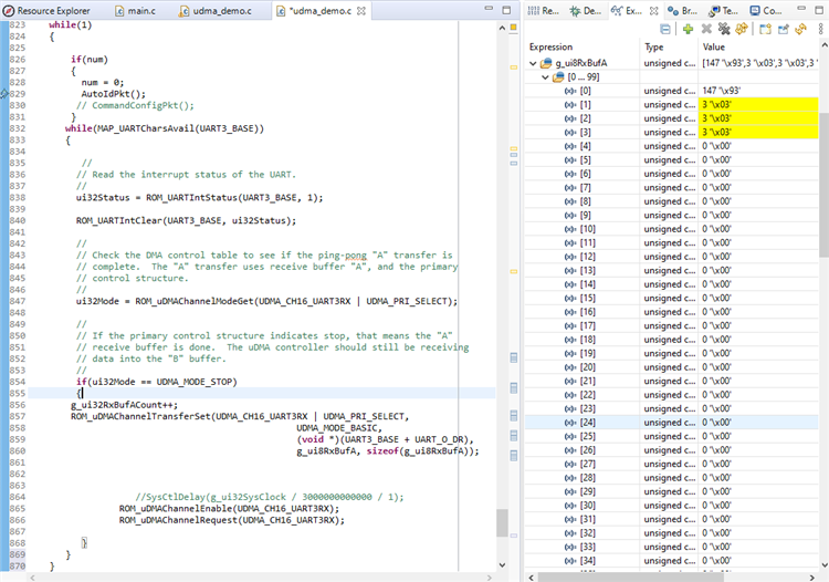
I'm working on EK-TM4C1294XL on DMA receive with UART using polling method. I'm sending 3 bytes of packet from TM4C eval board to another msp430 board, I want to receive those bytes on RxBufferA from Data register. When i run the code i'm getting 147,3,3,3. but i need to get 147,1,17. Am i missing something in configuration or anywhere? can someone guide me in a right way. Below is the code and output following where bytes in yellow are repeated in RxBufA instead 147,1,17.
void
uDMAIntHandler(void)
{}
/*****************************************************************/
void
UART3IntHandler(void)
{}
/*****************************************************************/
void
InitUART3Transfer(void)
{

    //
      // Enable the GPIO Peripheral used by the UART.
      //
      ROM_SysCtlPeripheralEnable(SYSCTL_PERIPH_GPIOA);


      //
      // Enable processor interrupts.
      //
      ROM_IntMasterEnable();

      //
      // Configure GPIO Pins for UART mode.
      //
      ROM_GPIOPinConfigure(GPIO_PA4_U3RX);
      ROM_GPIOPinConfigure(GPIO_PA5_U3TX);
      ROM_GPIOPinTypeUART(GPIO_PORTA_BASE, GPIO_PIN_4 | GPIO_PIN_5);

    //
    // Enable the UART peripheral, and configure it to operate even if the CPU
    // is in sleep.
    //
    ROM_SysCtlPeripheralEnable(SYSCTL_PERIPH_UART3);

    //
    // Configure the UART communication parameters.
    //
    ROM_UARTConfigSetExpClk(UART3_BASE, g_ui32SysClock, 1000000,
                            UART_CONFIG_WLEN_8 | UART_CONFIG_STOP_ONE |
                            UART_CONFIG_PAR_NONE);

    //
    // Set both the TX and RX trigger thresholds to 4.  This will be used by
    // the uDMA controller to signal when more data should be transferred.  The
    // uDMA TX and RX channels will be configured so that it can transfer 4
    // bytes in a burst when the UART is ready to transfer more data.
    //
    ROM_UARTFIFOEnable(UART3_BASE);
    ROM_UARTFIFOLevelSet(UART3_BASE, UART_FIFO_TX4_8, UART_FIFO_RX4_8);

    //
    // Enable the UART for operation, and enable the uDMA interface for both TX
    // and RX channels.
    //
    ROM_UARTEnable(UART3_BASE);

    ROM_UARTDMAEnable(UART3_BASE, UART_DMA_RX | UART_DMA_TX);

    //
    // Put the attributes in a known state for the uDMA UART1RX channel.  These
    // should already be disabled by default.
    //
    ROM_uDMAChannelAttributeDisable(UDMA_CH16_UART3RX,
                                    UDMA_ATTR_ALTSELECT | UDMA_ATTR_USEBURST |
                                    UDMA_ATTR_HIGH_PRIORITY |
                                    UDMA_ATTR_REQMASK);

    //
    // Configure the control parameters for the primary control structure for
    // the UART RX channel.  The primary contol structure is used for the "A"
    // part of the ping-pong receive.  The transfer data size is 8 bits, the
    // source address does not increment since it will be reading from a
    // register.  The destination address increment is byte 8-bit bytes.  The
    // arbitration size is set to 4 to match the RX FIFO trigger threshold.
    // The uDMA controller will use a 4 byte burst transfer if possible.  This
    // will be somewhat more effecient that single byte transfers.
    //
    ROM_uDMAChannelControlSet(UDMA_CH16_UART3RX | UDMA_PRI_SELECT,
                              UDMA_SIZE_8 | UDMA_SRC_INC_NONE | UDMA_DST_INC_8 |
                              UDMA_ARB_4);

    //
    // Put the attributes in a known state for the uDMA UART1TX channel.  These
    // should already be disabled by default.
    //
    ROM_uDMAChannelAttributeDisable(UDMA_CH16_UART3RX,
                                    UDMA_ATTR_ALTSELECT |
                                    UDMA_ATTR_HIGH_PRIORITY |
                                    UDMA_ATTR_REQMASK);

    //
    // Set the USEBURST attribute for the uDMA UART TX channel.  This will
    // force the controller to always use a burst when transferring data from
    // the TX buffer to the UART.  This is somewhat more effecient bus usage
    // than the default which allows single or burst transfers.
    //
    ROM_uDMAChannelAttributeEnable(UDMA_CH17_UART3TX, UDMA_ATTR_USEBURST);

    //
    // Configure the control parameters for the UART TX.  The uDMA UART TX
    // channel is used to transfer a block of data from a buffer to the UART.
    // The data size is 8 bits.  The source address increment is 8-bit bytes
    // since the data is coming from a buffer.  The destination increment is
    // none since the data is to be written to the UART data register.  The
    // arbitration size is set to 4, which matches the UART TX FIFO trigger
    // threshold.
    //
    ROM_uDMAChannelControlSet(UDMA_CH17_UART3TX | UDMA_PRI_SELECT,
                              UDMA_SIZE_8 | UDMA_SRC_INC_8 |
                              UDMA_DST_INC_NONE |
                              UDMA_ARB_4);

    //
    // Now both the uDMA UART TX and RX channels are primed to start a
    // transfer.  As soon as the channels are enabled, the peripheral will
    // issue a transfer request and the data transfers will begin.
    //
    ROM_uDMAChannelEnable(UDMA_CH16_UART3RX);
    ROM_uDMAChannelRequest(UDMA_CH16_UART3RX);
    ROM_uDMAChannelEnable(UDMA_CH17_UART3TX);
    ROM_uDMAChannelRequest(UDMA_CH17_UART3TX);

    //
    // Enable the UART DMA TX/RX interrupts.
    //
    ROM_UARTIntEnable(UART3_BASE, UART_INT_DMARX);

    //
    // Enable the UART peripheral interrupts.
    //
    ROM_IntEnable(INT_UART3);
}

/*****************************************************************/

int
main(void)
{
    uint32_t ui32Status;
    uint32_t ui32Mode;
    //
    // Set the clocking to run directly from the crystal at 120MHz.
    //
    g_ui32SysClock = MAP_SysCtlClockFreqSet((SYSCTL_XTAL_25MHZ |
                                             SYSCTL_OSC_MAIN |
                                             SYSCTL_USE_PLL |
                                             SYSCTL_CFG_VCO_480), 120000000);

    //
    // Enable peripherals to operate when CPU is in sleep.
    //
    ROM_SysCtlPeripheralClockGating(true);


    //
    // Enable the uDMA controller at the system level.  Enable it to continue
    // to run while the processor is in sleep.
    //
    ROM_SysCtlPeripheralEnable(SYSCTL_PERIPH_UDMA);

    //
    // Enable the uDMA controller error interrupt.  This interrupt will occur
    // if there is a bus error during a transfer.
    //
    ROM_IntEnable(INT_UDMAERR);

    //
    // Enable the uDMA controller.
    //
    ROM_uDMAEnable();

    //
    // Point at the control table to use for channel control structures.
    //
    ROM_uDMAControlBaseSet(pui8ControlTable);

    //
    // Initialize the uDMA UART transfers.
    //
    InitUART1Transfer();

    //
    // Loop until the button is pressed.  The processor is put to sleep
    // in this loop so that CPU utilization can be measured.
    //
    while(1)
    {

        if(num)
        {
          num = 0;
          AutoIdPkt(); // My 3 bytes packet(147,1,17)
        }
       while(MAP_UARTCharsAvail(UART3_BASE))
       {

          //
         // Read the interrupt status of the UART.
         //
         ui32Status = ROM_UARTIntStatus(UART3_BASE, 1);

         ROM_UARTIntClear(UART3_BASE, ui32Status);

         //
         // Check the DMA control table to see if the ping-pong "A" transfer is
         // complete.  The "A" transfer uses receive buffer "A", and the primary
         // control structure.
         //
         ui32Mode = ROM_uDMAChannelModeGet(UDMA_CH16_UART3RX | UDMA_PRI_SELECT);

         //
         // If the primary control structure indicates stop, that means the "A"
         // receive buffer is done.  The uDMA controller should still be receiving
         // data into the "B" buffer.
         //
         if(ui32Mode == UDMA_MODE_STOP)
         {
        g_ui32RxBufACount++;
        ROM_uDMAChannelTransferSet(UDMA_CH16_UART3RX | UDMA_PRI_SELECT,
                                                  UDMA_MODE_BASIC,
                                                  (void *)(UART3_BASE + UART_O_DR),
                                                  g_ui8RxBufA, sizeof(g_ui8RxBufA));

                 ROM_uDMAChannelEnable(UDMA_CH16_UART3RX);
                 ROM_uDMAChannelRequest(UDMA_CH16_UART3RX);

          }
       }
    }
}

