This thread has been locked.

If you have a related question, please click the "Ask a related question" button in the top right corner. The newly created question will be automatically linked to this question.

FAST FOC Phase current shape

Guru 54027 points
Part Number: LAUNCHXL-F280049C
Other Parts Discussed in Thread: MOTORWARE, INA240, BOOSTXL-DRV8320RS, DRV8312

SDK v2.01

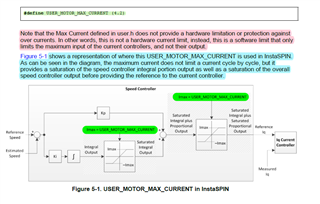
Last posted questions how Clarke transform/s should format I/V alpha/beta for FAST FOC estimator to produce theta angles output for Park transform.

Lab7 has RsRecalculation flag = false (labs.h) and we know ADC offset calculation auto runs enabling SYS prior to set Online = 0x1.

      motorVars.flagEnableOffsetCalc = true;

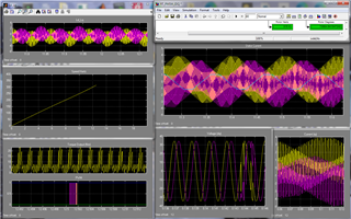
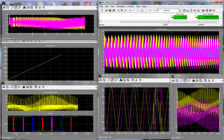
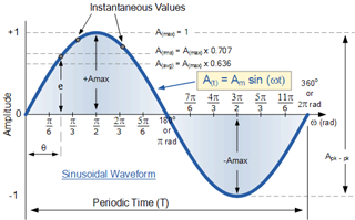
Phase A is producing current shape below (Angular) pattern, indicates bypass RsReCalibration is enabled prior to closed loop? Lab7 OnLine flags are false prior to mainISR, SVGEN_run(), default for Lab7 speed control. It seems FAST estimator mandates RsRecalibration be force enabled during closed loop SVG_run() otherwise phase A current becomes Angular and not Sinusoidal?

Figure 10-8 shows the current and output voltage waveforms when offsets and Rs recalibration is bypassed.

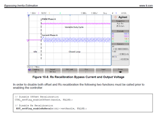
10.4 Startup with No Re-calibration
This startup approach is the fastest method to get the motor running in closed loop. It does not recalibrate offsets or resistance. As soon as the controller is enabled, the motor is run in closed loop. This method should only be used when the offsets and stator resistance are well known. For details of how to handle full-load conditions at start-up, see Chapter 14. Figure 10-7 shows how the motor is run in closed loop right after the idle state, without any recalibration.

 //
//! \brief Initialization values of global variables
//
#define MOTOR_VARS_INIT {                                                      \
    false, /* flagEnableSys */                                                 \
    false, /* flagEnableRunAndIdentify */                                      \
    false, /* flagRunIdentAndOnLine */                                         \
    false, /* flagMotorIdentified */                                           \
    false, /* flagSetupController */                                           \
    true,  /* flagEnableForceAngle */                                          \
                                                                               \
    false, /* flagEnableRsRecalc */                                            \
    false, /* flagEnableRsOnLine */                                            \
    false,  /* flagEnableUserParams */                                          \
    true,  /* flagEnableOffsetcalc */                                          \
    false, /* flagEnablePowerWarp */                                           \
    true,  /* flagBypassLockRotor */                                           \
                                                                               \
    true,  /* flagEnableSpeedCtrl */                                           \
    true,  /* flagEnableCurrentCtrl */                                         \
    MOTORCTRL_MODE_SPEED,  /* motorCtrlMode */          


        if(EST_isMotorIdentified(estHandle) == true)
        {
            if(motorVars.flagSetupController == true)
            {
				/* Disable Online Rs Recalibration */
			    //? motorVars.flagEnableRsRecalc = false;
                //
                // update the controller
                // set custom current and speed controllers gains
                //
                updateControllers();
            }
            else
            {
                motorVars.flagMotorIdentified = true;
                motorVars.flagSetupController = true;
				/* Enable Online Rs Recalibration */
				//? motorVars.flagEnableRsRecalc = true;

                setupControllers();
            }
        }

  • It would seem the angular shape (phase A current) occurs when RsRecalibration (is not) bypassed, rather than bypassed as stated SPRUHJ1H–January 2013–Revised June 2019.

    The odd thing being RsRealibration is (false). Yet phase A current looks close to Saw tooth wave omitting rise/fall slopes Fig.10-8. Phase B and Phase C have very fairly nice sinusoidal slopes in the rise and fall times. 

    Update: Online RsReCalibration asserts default enabled unless estimator is specifically directed Lab7, thus it ignores user.h bool flag setting.   

  • The A/V offset calibration seems to be running background, EPWM1 (phaseA) has added 10µs on/off duty cycle. Hence phase A has angular shaped phase current (Fig.10-8) also occurs if controller offset calibration is left enabled. Coincidence seemingly not.... 

    The controller has never really disabled offsets (lab5, Lab7) runOffsetsCalculation() fails to update controller A/V values, where ever logic block exists. I modified Lab7 RsOnlineRecalibration to disable >1Hz as to achieve maximum start torque, then disable after. Point being RsOnlineRecalibration() is not the issue, rather Offsets calculation of controller seems to be enabled during Fast estimator angles for phase A.

            //
            // run the space vector generator (SVGEN) module
            //
            SVGEN_run(svgenHandle, &Vab_out_V, &(pwmData.Vabc_pu));
    
            /* Check rotor speed >1Hz, and disable Force Angle flag */
             if((motorVars.speed_Hz > USER_FORCE_ANGLE_FREQ_Hz) &&
             		(motorVars.flagEnableForceAngle == true))
             {
             	/* Disable estimator Force Angle speed >1Hz */
                EST_setFlag_enableForceAngle(estHandle, false);
                /* Update the motor parameter flag value */
                motorVars.flagEnableForceAngle = false;
    
                /* Disable Online RsRecalibration flag */
                motorVars.flagEnableRsOnLine = false;
                /* Disable estimator RsOnline control algorithm  */
                EST_setFlag_enableRsOnLine(estHandle, motorVars.flagEnableRsOnLine);
                /* Get last Online coil ohms sent to estimator */
                motorVars.RsOnLine_Ohm = EST_getRsOnLine_Ohm(estHandle);
             }


  • Oddly Lab7 SVGEN_run() code (above) returns perhaps a few times then loops in return address pushed on the stack and never reaches the &PWMdata loads to update CMPA . The entry statement if(motorVars.flagEnableOffsetCalc == false) of mainISR loop is an orphaned interrupt re-entrant only to the last pushed return address. So it never falls through to assert the remaining few calls at the bottom of the mainISR loop mainly this one below.

    //
    // write the PWM compare values
    //
    HAL_writePWMData(halHandle, &pwmData);

    Seems to explain why CMPA shadow value is not being updated but only 1 time. 

    Put this call anywhere above &pwmData write. It only updates debug Expressions cell idle time of motorVars.flagEnableSys = 0x1.

      /* Get last Online coil ohms sent to estimator */
    motorVars.RsOnLine_Ohm = EST_getRsOnLine_Ohm(estHandle); 

  • Thanks for so detailed content you posted above. It seems like there are different topics in this thread, could you tell me what's your questions directly?

  • I was reporting Lab07 issues, Then discovered RsOnlineRecalibration must be enabled for Lab7 but was not true labs.h. Enabling PI speed control mandates to enable RsOnlineRecalibration prior to motor start. 

    Yet it seemed incorrect to leave RsOnlineRec enabled once the motor speed >1Hz, but is good to check each time the motor is restarted. Why is the last Online RsReCalibration as the above code method not reporting accurate motorVars.RsOnLine_Ohm? The returned value is often >3 times the real phase coil resistance. 

    Symptoms:

    Online RsRecalibration was disabled and there was no slow speed start torque, 10Hzps trajectory speed. Coincidentally phase A was producing saw tooth current shown in posted figure, phase B, phase C were not. Was the controller offset calculation enabled all the time since the shape of phase A current remained the same as figure shows, very sharp peaks? The current is not evenly distributed between 3 phases.

    Note both calibrations have to be disabled to abort or end DC injection into phase A.  That generates saw tooth current on phase A according to SPRUHJ1H–January 2013–Revised June 2019. The reason to trouble shoot the offset ReCalibration, AKA offset ReCalculation was moved into Lab07 contrary to documented text. Note it does not say Phase B or C, only shows phase A specifically has saw tooth wave shape.

    EPWM1 also has a variable duty cycle 10µs >EPWM2 or >EPWM4 similar to posted figure again, it should not! CMPA is loaded with the same period in each cycle and phase A (EPWM1) should have the same duty cycle as phase B (EPWM2) and phase C (EPWM4).

    How is it possible given the coil resistance are near identical Phase A current remains more saw tooth shape and much lower magnitude? If Clarke transform and CMPA period loads are working correctly all 3 phases should have fairly even current distribution.

  • Phase A current is very saw tooth shape at low speed (60-80Hz) and gradually gains some small arcs in the rise/fall times. Why only phase A is mostly saw tooth shape current? The phase B, C have similar inflection distortions near 140Hz. Some current THD is gate drive propagation delay related but not all. 

    HAL_writePWMData() reading TBPRD register (for loop) writing CMPA match values, even via shadow loads (CTR=0/CTR=TBPRD) refuse to synchronize match counts evenly between EPWM generators. The C++ read after write (RAW) registers via (for loop) is not working so well in this area of code.

    To many random match counts for same 25µs period between any two phases makes for odd shaped unstable current? What is a good work around WA? Seemingly linking slaves to master CMPA would be as to gain even matches and omitting (for loop). The TBCTR is still counting during each CMPA match count load, even via shadow load events.

    Yet  linking CMPA 2 Slaves of single Master EPWM generates random shapes of phase current. Perhaps ADC Isense acquisitions EOC interrupt times diverge?

  • Rs online calibration is disabled in lab07 by default, only lab10, and subsequent labs enable and support the Rs online calibration.

    The value of the PWM period register is fixed and will be not changed in all of the labs except lab12, and CMPA is set to shadow load mode by updating at TBCTR=0. 

  • Yet Lab07 failed to start motor 10Hzps with PI enabled and trajectory interrupt tick=1, can be 2 ticks with Rs running on startup <1Hz. It takes several seconds for motor to start, rotor rocks back and forth few degrees. Why CMPA phase A has 10µs> duty cycle than phase B or C and sharp current peaks as Fig.10-8? The Vsense (A,C,B) into ADC channels are of equal magnitude.

    Seemingly BoostXL started motor Lab7 with ID low inductance value, current peaks >USER_MOTOR_MAX_CURRENT_A value. There is a huge difference between 200µH and 980µH when Vsense order changed to A,C,B and points to Clarke inputs array math.  

    Checking over FCL code, Clarke multiplies ADC phase current * ADCScale * 1/√3 and has no typedef pointer names for SDK use. Not sure what the intent was to add FCL code that conflicts with SDK design. 

    Note FCL uses ADC PPB register for current, not EOC sample value.

    //
    // FCL MACRO implementing CLARKE transform on currents using pointers to
    // registers used in both PI CONTROL and COMPLEX CONTROL
    //
    #define FCL_CLARKE_STYLE_1()                                                   \
        clarke1Alpha = (float32_t)((int16_t)HWREGH(curA_PPBRESULT) *               \
                                FCL_params.adcScale);                              \
        clarke1Beta  = ((clarke1Alpha +                                            \
                         (2.0 * ((float32_t)((int16_t)HWREGH(curB_PPBRESULT)) *    \
                          FCL_params.adcScale))) * ONEbySQRT3);
    
    //
    // FCL MACRO implementing CLARKE transform on currents using bit field type
    // register access used in both PI CONTROL and COMPLEX CONTROL
    //
    #define FCL_CURRENT3_A  (IFB_LEMV_PPB * FCL_params.adcScale)
    #define FCL_CURRENT3_B  (IFB_LEMW_PPB * FCL_params.adcScale)
    
    #define FCL_CLARKE_STYLE_3()                                                   \
            clarke1Alpha = (FCL_CURRENT3_A);                                       \
            clarke1Beta  = ((clarke1Alpha + (2.0 * FCL_CURRENT3_B)) * ONEbySQRT3);


  • Note phase A current appears similar to older Ld/Lq analysis plots of same motor made years ago. Accept SDK torque/speed falls behind projected values for the same DC bus supply and inertia kgm^2. Below modulation perhaps THIRSVPWM, a single triangle wave generator is switched into PWM block, drives NFETS. Phase A (blue) trace runs outside phases (B/C), is either high or low as B/C phases modulate much faster.

    Angle is 3.3°, 18 pole pairs, coil 0.57Ω. The SDK speed reaches 140Hz peak, seemingly speed frequency should reach higher 42vdc. The dq/iq below match closely with SDK accept adcData.V_V  leverages Lab07 ADC offsets. Perhaps PPB -offsets of bipolar recreation has greater precision signing negative Vsense levels? I fixed the HAL_ADC offset calibration code for 16 channels OffTrim(0xCC2) no great bananas Cry.


  • PPB is not used in Instaspin labs as FCL. The instapsin lab read the value of the ADC result and convert it to floating-point with SI unit, and then remove the offset for Clark input.

    Using PPB or ADC result has the same resolution, just the PPB has a function to remove the offset directly.

  • with SI unit

    P.U. is per unit value, not sure what the SI unit refers to other than FCL module is enabled. 

    and then remove the offset for Clark input.

    Yet the Bipolar Vdq still goes into Clarke as if it was intentional. The ADC offsets now produces ± half cycles into Clarke. 

    The instapsin lab read the value of the ADC result and convert it to floating-point with SI unit, and then remove the offset for Clark input.

    The ADC offsets use motorVars.Vbus_sf = (motorVars.offset_invVbus_invV * adcData.dcBus_V) the value FCL floats decimal point right by mistake, calculator math proves SF is roughly 2.016xxx, not 20.16xxxx. The following statement labs.h (1.0 / VBUS_OFFSET_V), /* offset_invVbus_invV or 1/21v=0.048 */ 

    Vsense into PPB will provide Bipolar results without inline Offset calculations wasting CPU cycles. The ADC Vdq Offset peaks are much lower than Bus voltage, seemingly result of incorrect SF floating multiplication error. CCS real time debug watch shows SF 10x greater, is that intentional? 


  • The ADC offsets now produces ± half cycles into Clarke

    After code patch Lab7 passes all negative values to Clarke. The Vdq was bipolar in simulations, does FAST expect bipolar alpha/beta? I'd be less concerned if the values (red box) were ± to Clarke after patching. The point FAST to generate better sinusoidal shape phaseA current.

    Vdq RMS samples 0.707 peak seemingly a boundary for DPWM1 rotation angle points involve ADC scale factors. SDK seems to have Mi0.5 HDF, the >Mi=0.9 but at what PWM frequency 15-20kHz, 50-100kHz? Why to make Mi>0.5 via MATH_sat(V_pu, (float32_t)0.8, (float32_t)-0.8) and FAST estimator does not produce a precision angle in this range? I realize DPWM is newer sector rotation method for x49c and SVPWM was for previous Motorware MCU classes. That is my perception of why there are very few answers to harder questions today. 

        adcData.V_V.value[0] -= (motorVars.offsets_V_V.value[0] * adcData.dcBus_V);//motorVars.Vbus_sf;
        adcData.V_V.value[1] -= (motorVars.offsets_V_V.value[1] * adcData.dcBus_V);//motorVars.Vbus_sf;
        adcData.V_V.value[2] -= (motorVars.offsets_V_V.value[2] * adcData.dcBus_V);//motorVars.Vbus_sf

  • The SI base units are the standard units of measurement defined by the International System of Units (SI).

    Yes, the PU format is used in the FCL project, but the instapsin projects use the SI unit in motorcontrolSDK.

    Yes, the output Vdq could be a positive or negative value that depends on the reference Id/Iq current and controlling state.

    The offset voltage is used to eliminate the sampling circuit error between three phases. What value is the motorVars.offsets_V_V.value[0/1/2]?

  • Yes, the PU format is used in the FCL project, but the instapsin projects use the SI unit in motorcontrolSDK.

    Yet the pu naming convention is all over the SDK FOC code especially where the DPWM method concatenates rotation sector data for CMPA. Perhaps it's more like SIPU what ever that is Thinking

    motorVars.offsets_V_V.value[0/1/2]

    //! \brief ADC voltage offsets for A, B, and C phases
    #define VA_OFFSET_V (0.999343634) // ~=1.0
    #define VB_OFFSET_V (0.998467565) // ~=1.0
    #define VC_OFFSET_V (0.999186754) // ~=1.0

    Yes, the output Vdq could be a positive or negative value that depends on the reference Id/Iq current and controlling state.

    Yet the bus_volts patch removal of SF made Vdq signs remain all negative. Also removed {motorVars.offset_invVbus_invV = 0.5;} Lab07 line 371 then SF math works (green box) lower values. The Vdq offsets seem to work better adding to ADC sample. Current is more stable and PI does not over/under shoot the trajectory target as wildly. Now the Vdq values remain positive and have a large window nearly full bus voltage. It seems FAST is not doing anything much with the sign changes anyway.

     adcData.V_V.value[0] += (motorVars.offsets_V_V.value[0] * motorVars.Vbus_sf); //adcData.dcBus_V
    adcData.V_V.value[1] += (motorVars.offsets_V_V.value[1] * motorVars.Vbus_sf); //adcData.dcBus_V
    adcData.V_V.value[2] += (motorVars.offsets_V_V.value[2] * motorVars.Vbus_sf); //adcData.dcBus_V


  • The offset is for three-phase current and voltage at a/b/c frame, not Vdq. As replied to you in another thread, the voltage offset is used to eliminate the error between the three-phase voltage sampling deal circuit. The Clark transform will eliminate the common offset value.

  • the voltage offset is used to eliminate the error between the three-phase voltage sampling deal circuit

    The point is the offset wrongly subtracts from the ADC sample, that will lower the Vdq into Clarke. Adding the channle offset improves sector angle and inductive current shape becomes more sinusoidal. It simply doe not seem logical to subtract channel offsets, that puts the voltage below the starting analog float value level. 

    Any idea why phase A has constant triangle shape? Might it be better to distribute PWM more evenly across 6 inverter switches. Oddly the current is level shifting phase to phase. It seems EPWM phase shift control should achieve better SVPWM distribution.

  • Let's use standard symbols, the input of Clark is Va/c/c or Ia/c/b on (a, b, c) frame, not the Vdq or Idq. As replied to you, I don't think the offset is subtracted incorrectly in the labs. Of course, you can try everything you want since these codes are open source and just a reference for you.

    The three-phase voltage has an approximately trapezoidal shape when sampling the voltage with a low-frequency filter.

    Could you please post some figures that could help us to understand your questions? Thanks!

  • As replied to you, I don't think the offset is subtracted incorrectly in the labs.

    The Ia,b,c offsets seem ok since sample data is for arguments sake (bipolar) 0v=2048 count. Yet SDK current offset values are much > (Fig.6.8) show SPRUHJ1H–January 2013–Revised June 2019 . In fact the ADC current offsets being the inverse of FullScaleADCCurrent is never even discussed. Technically your point lacks any substantial written disclosure to prove SDK code is even proper to being with.

    Example the INA240 output signal threshold is 40-80mV above ground rail, about  PGA's what is their signal offset from ground rail? Channel offsets needs to accounted for but seems to be ignored or lumped into less than precise SDK current regulation.

    Semantically Va,b,c are uni-polar ADC values that threshold at channel offset levels, not below offset. Subtracting Va,b,c offsets does not improve precision of the channel analog value, it just reduces the real ADC count by the offset amount (threshold). Need to add the offset into the ADC counts to clarify the channel signal floor (0v) exist above ADCOFFTRIM register trim values. 

    6.5.2 The offsets calculation is done in order to set the zeros for current measurements and voltage measurements. In order to calculate the offsets, a 50% duty cycle is set on the EPWM pins for a preconfigured period of time. The time in which these offsets are calculated can be changed by the user, and it is configured in user.c file as shown below: 

    Why does altering TBPRD period registers (below code) also do not correct current regulation of SVM rotation calculations? It seems the PWM duty cycle CMPA is not synchronized with ADC samples (Ia,b,c) of sector rotation angles and one or two phases carry largest current load. The promise of DSPWM even current distribution with reduced (THD) is not met via, Mi=0.5=USER_MAX_VS_MAG_PU. Why does TBPRD register control not lower the individual EPWM duty cycles and instead chops up current causing harmonics?

    With this posted case; phase A (Master EPWM1) has the least load, phase B (EPWM2 slave) doubles load of A, phase C (EPWM4 slave) nearly triples current load or C+B. The TBPRD EPWM2/4 registers are reverse phase order (A,C,B) and documented incorrectly BoostXL-drv8320rs quick start guide. Why is the order not as depicted { SPRUI33D – NOVEMBER 2015 – REVISED SEPTEMBER 2020 Figure 18-68, Control of Dual 3-Phase Inverter Stages as Is Commonly Used in Motor Control} ?? 

         #if (BOOST_to_LPD == BOOSTX_to_J5_J6)
        // initialize PWM handles for Motor 1
        obj->pwmHandle[0] = EPWM1_BASE;       //!< the PWM handle, GPIO0/GPIO1
        obj->pwmHandle[1] = EPWM4_BASE;       //!< the PWM handle, GPIO6/GPIO7
        obj->pwmHandle[2] = EPWM2_BASE;       //!< the PWM handle, GPIO2/GPIO3


            // since EPWM is set up/down counter, the period register is
            // set one-half the desired TBPRD period as starting duty cycle
            // Note: Shadow of TB period register is configured above.
            EPWM_setTimeBasePeriod(obj->pwmHandle[0], halfPeriod_cycles); //phaseA:2500 or 25µs
            EPWM_setTimeBasePeriod(obj->pwmHandle[1], halfPeriod_cycles * (float32_t)0.75); //phaseC:2125
            EPWM_setTimeBasePeriod(obj->pwmHandle[2], halfPeriod_cycles * (float32_t)0.85); //phaseB:1875
     

  • Yes, the offset calibration mode and value will be different from the current sensing deal circuit. We just provide the reference code based on the related EVM kit.

    The voltage offset is calibrated when three-phase PWM duties are set to 50%, at this moment, the phase voltage should be equal to half of the Vdc bus voltage and the phase current equals zero.

    Generally, it seems like the three-phase PWM periods are the same value and the PWM clock should be synchronized in a three-phase motor with FOC. Of course, you can try the phase-shift control as you mentioned above.

  • The voltage offset is calibrated when three-phase PWM duties are set to 50%, at this moment, the phase voltage should be equal to half of the Vdc bus voltage and the phase current equals zero.

    Also tripping DAC faults during offset calibration, only known that occurs by clearing EPM trip zone faults after function entry. The 50% offset calibration duty cycle is being picked up by CMPSS DACH/L events.

    Of course, you can try the phase-shift control as you mentioned above.

    It's not phase shifted with 0x0 value, only enabled. The period cannot be reduced on EPWM generators without affecting Mi0.5 ~MAG_PU. The sector control algorithm perhaps needs to monitor EPWM periods/cycles in the ADC full scale current range, not let just let them go wild. The Pi controller is perhaps a suspect to control duty more evenly, what do you think?

  • The 50% offset calibration duty cycle is being picked up by CMPSS DACH/L events.

    Note SDK v3.01 changed the bus voltage divisor from 2 to 1. Though offsets hardly manifest as being phase current limiting calculations. 

    Regarding PhaseA Triangle wave; It moves to center phase-B when -A is switched to -C wire post, motor direction changes. Then Phase-A has the most current, -B the least and -C next highest current. And again center phase B now has triangle shaped current pattern.

    Note the offset calculation as defined section 6.5.2 (SPRUHJ1H) Pg.254 below. If you subtract the offset then goes reason to do offset calculation to begin with. The Vsense offset values (~0.9v) seems very high in earlier calibrations via inverse dcBus_V/2 compared to Fig.6-9.

    The offsets calculation is done in order to set the zeros for current measurements and voltage measurements. In order to calculate the offsets, a 50% duty cycle is set on the EPWM pins for a preconfigured period of time. The time in which these offsets are calculated can be changed by the user, and it is configured in user.c file as shown below:

    pUserParams->ctrlWaitTime[CTRL_State_OffLine]=(uint_least32_t)(5.0*USER_CTRL_FREQ_Hz);

    In the example above, the offsets calibration is done for a period of 5 seconds. Although 5 seconds for offset calibration is enough for most of the hardware, if the user requires a shorter or longer time for their particular needs, simply change the 5.0 value of the line of code above, and the time to do offset calibration will change according to the new setting. Once the offset calibration is done, the final result will be stored in the driver object (HAL_Obj). For more details about HAL_Obj, see Table 8-1. Figure 6-9 shows the final results of calibrating the offsets for the DRV8312 Revision D board.

  • Later test SDK with 100vdc Bus_volts, calculate resistor divider for ADC scale factors etc. Top speed 265Hz, current is excessively high 11-12 amps 275Hz one phase only. Something seems off no matter how offsets are determined with or without scale factor, current becomes unstable.

    The rotor flux sounds like counter torque invades sector angles then flux wants to crash as current becomes extreme, in one phase. Typically SPM motor reaches 1850 rpm via trapezoidal 6 step FOC and 1650 rpm 100vdc. What is the advantage of SDK sensorless FOC that uses more battery current to achieve even lessor speed torque?

    Instaspin estimator is great to start any sensorless motor but SDK should switch to produce trapezoidal current >1Hz rotor speed.

    Why this SVM can not achieve any speed and uses excessive battery current? Seemingly FAST estimator omits far to many mechanical electrical angles required to produce proper magnetic ld/lq drive flux. Same SPM motor via 6 step sensorless FOC trapezoidal modulation goes much faster with good torque too. For every 20vdc added to Vbus rotor speed improves 30-50 rpm or more. The current below is via RMS float 0.707 of peak Min/Max.


  • The significant advantage of sensorless FOC is that the output torque is more stable with a lower ripple than trapezoidal control.

    The phase current of the motor is not equal to the dc current of the battery. The FAST estimator needs precise motor parameters to achieve a better invert efficiency and run the motor to a high speed.

  • The significant advantage of sensorless FOC is that the output torque is more stable

    Yet the motor can not reach the similar speeds in the absence of torque ripple or missing commutation events. The real motor magnetic torque is not reaching near FEA modeled simulation results (above) thus maximum speed torque is greatly reduced. Oddly the simulation triangle wave generator impacts one phase of stator current via slower PWM modulation times.

    Yet there is no real current regulation Lab13 and wiping out 80A NFETS seems to be the result of slow Pi control. The integral of kgm2 formula is not exactly science based or even tested with larger motors. Deadband was 180ns, never have any problem with FOC trapezoidal and shoot through.  

    The SDK is completely different from PDF text: SPRUHJ1H 5.1.8: USER_MAX_VS_MAG_PU can go up to 1.0, in global IQ format, or _IQ(1.0), if current reconstruction is not used

    The over modulation region for current reconstruction Lab13 has issues with Pi block controls and larger motor kgm2 values are unstable. FW does not work at all, no matter the 3 input values.  Compared with trapezoidal FOC there is no need for kgm2 values. The SDK saturation control reacts slower when Pi aperture (BW/delta/rps) must be widened to arrest crashing flux as current nears Max Vsense speed. Something in the SDK Mi0.5 does not follow the same modulation rules as past documented.    

    The phase current of the motor is not equal to the dc current of the battery.

    5.1.4: Max Current Fig.5-1 shows a representation of where this USER_MOTOR_MAX_CURRENT is used in InstaSPIN. As can be seen in the diagram, the maximum current does not limit a current cycle by cycle, but it provides a saturation of the speed controller integral portion output as well as a saturation of the overall speed controller output before providing the reference to the current controller.

    The  {USER_MOTOR_MAX_CURRENT_A = (10.5)} So how did Pi values short out 80 amp NFETS? Why does code (below) modification cause Pi mayhem? Why does kgm2 have to be modified to arrest flux crashing that becomes worse as higher Bus voltage applied? The HV kit leverages an costly IGBT module (saturates) thus comparing oranges to apples as NFETS enter into transconductance. Does the SDK support only IGBT's with higher Bus voltages, doubtful Rolling eyes

    Modified Ki/Kp_Spd values (SDK v2.01) widens the Pi BW_delta/rps apertures.

    #if(USER_MOTOR_INERTIA_EN)
        	/* Lab7 determined BW required for Kp_spd/Ki_spd */
            pUserParams->BWc_rps = MATH_TWO_PI * (float32_t)130.0; //Proportion Filter pole: rads/sec
            pUserParams->BWdelta = (float32_t)60.0; // Integral
            
            
        float32_t BWdelta = userParams.BWdelta;
        float32_t Kctrl_Wb_p_kgm2 = (float32_t)3.0 *
                                  userParams.motor_numPolePairs /
                                  userParams.motor_ratedFlux_Wb /
                                  (float32_t) (USER_MOTOR_INERTIA_Kgm2 / 2);
                                  //was Kgm2*2, * numPolePairs        

  • The FAST estimator needs precise motor parameters to achieve a better invert efficiency and run the motor to a high speed.

    Thinking hats on visual aid to help discussion of SDK current control for larger kgm2 inertia values. The SDK is unstable for large motor kgm2 inertia values in it's current versioning code state, no pun intended Grin

  • output torque is more stable with a lower ripple than trapezoidal control.

    Yet a small part of magnetic torque ripple is still required (simulation) to produce better rotor velocity with minimal battery current. With trapezoidal FOC the left hand generator rule comes into play, during switch off phase times. Magnetic potential does not always require battery current to produce torque, seemingly results in magneto (instantaneous) current generation.

    History fact, light houses 120 years past used magneto generators to power mercury vapor lamps.  

  • Thanks for having an introduction to these concepts. As discussed with you before, the calculation formula of the speed controller parameters is just for reference, and only is validated on some generic motors, you might have to tune these controller parameters case by case.

  • you might have to tune these controller parameters case by case.

    Right but as you can see that code change was done above but the Pi controller still has current control issues. There was minimal gate ringing to cause false turn on and 180ns off time should be more than enough dead time. The odder part is the CMPSSx did not trip zone EPWM current fault status, both times the center phase took a hit. After the first NFET short I reduced the OC trip point of 20A to 15A and it still did not trip OC fault. The last crash caused shoot through when Pi drove current controller into high frequency oscillations and crazy mouse right clicks CCS debug fail to disable Online state, toggles back 0x1 when clearly 0 was typed.

    That is good reason why LAB's need to use SCIA touch screen LCD for java script control pages. The not so isolated launchXL USB port failed as Debug crashes and red text screens put real time silicon control off line. In the panic forgetting reset button on launch pad can quickly arrest the god awful velocity commutation crashing. I'm not so sure debug was an ideal 1st control method as EMF kick back can get real messy. 

    only is validated on some generic motors

    Mostly small motors with less benefit to solar powered machines of the 21st century. Notice many posters are leveraging larger rotor masses to move people/package machines or refit AC line powered ones with DC battery powered. Watching PBS the "Great Electric Airplane Race" is a real eye opener too. 

    https://www.pbs.org/wgbh/nova/video/great-electric-airplane-race/

  • The Axiom open source project mentions some key points that TI should integrate as safety measures for use with CCS debug. Perhaps adopt VESC motor control interface and remove CCS debug as being the motor control and tuning source. The user.h motor parameter input method and project lab examples seem to skirt around more difficult tuning issues relative to FOC motor control.

    Axiom: 100+kW Motor Controller | Details | Hackaday.io

    VESC current controller: bldc/mcpwm_foc.c at 22dc2ce33c64593beb1e01a3b062d8c1df73beec · vedderb/bldc · GitHub

    • The FPGA is continuously monitoring all fault inputs. If any fault is asserted, all PWM activity is shut down.
    • FPGA supervises the PWM generated by the MCU. Shuts down PWM if a shoot-through command is detected

    The SDK Pi controller (Ki_spd,/Kp_spd) formula and current controller seemingly issued a shoot through command to SVGEN block. And 1 of 3 phases remains low speed triangle shaped. What causes triangle undocumented {SPRUHJ1H} current wave shape?

    Again swapping phase-A/C wire position made triangle wave move center 1/2 bridge and shoot through occurred during Pi flux crash. The rotor speed improved by 20Hz after swapping phases and triangle current wave moved center 1/2 bridge. The Pi kgm2 values were default via user.c me forgetting to un-comment motor real inertia values user.h. The conundrum of (user.h) motor parameters is ever unfolding & detrimental.  

     What caused center phase shoot through if current controller is saturated via {USER_MOTOR_MAX_CURRENT_A = (10.5)}?

  • My first guess to why would be the radiator has an analog leak Nerd.

    Clarke transform appears to do an illegal mathematical calculation. Math ordering requires multiplication and division are preformed before addition or subtraction within algebraic expressions or formulas. Clarke transform appears to violate proper ordering by first subtracting values within parentheses lastly multiplying.

    SDK method for Clarke transform does not follow basic math ordering rules and would likely produce alpha/beta values that are not exact. My Algebra II teacher would write chalk board short cuts for class to prove expression actually produced correct results upon working backwards. She had past worked for Ford motor company engineering and was genius level wiz kid if you ask me.

    Typical Clarke transform:

    * Full Clarke transform (no balanced voltages)
    * m_motor_state.v_alpha = (2.0 / 3.0) * Va - (1.0 / 3.0) * Vb - (1.0 / 3.0) * Vc;
    * m_motor_state.v_beta = ONE_BY_SQRT3 * Vb - ONE_BY_SQRT3 * Vc;

    Example:

    The SDK has beta_SF (1/sqrt3) multiplied after subtraction; {MathVec3 *pInvec} as (pInVec->value[1] - pInVec->value[2]) * beta_sf;

    An order based algebraic expression appears more like: (beta_sf * pInVec->value[1] ) - (beta_sf * pInVec->value[2]);

    The Order of Operations in Algebra – One Percent Growth

  • An improved Clarke algorithm lets motor cleanly reach 275Hz. Note Clarke handles Vsense and ISense analog input data for FAST estimator. So it must not have mathematical order compiled errors the x49c math co-processor might struggle with. Who knows what CCS compiler is doing to factor ordering? 

        //
        // Perform the Clarke transform for either 2 or 3 sensor setups
        //
        /**********************************************************************************
         * 	Full Clarke transform (no balanced voltages)
    	 *	m_motor_state.v_alpha = (2.0 / 3.0) * Va - (1.0 / 3.0) * Vb - (1.0 / 3.0) * Vc;
    	 *	m_motor_state.v_beta = ONE_BY_SQRT3 * Vb - ONE_BY_SQRT3 * Vc;
    	 **********************************************************************************/
        if(numSensors == 3)
        {
            pOutVec->value[0] =
            		 ((MATH_TWO_OVER_THREE * pInVec->value[0]) -
            				 (alpha_sf * pInVec->value[1]) - (alpha_sf * pInVec->value[2]));
    
            //((pInVec->value[0] * (float32_t) 2.0) - (pInVec->value[1] + pInVec->value[2])) * alpha_sf;
    
    
            pOutVec->value[1] = (beta_sf * pInVec->value[1]) - (beta_sf * pInVec->value[2]);
    
            //pOutVec->value[1] = (pInVec->value[1] - pInVec->value[2]) * beta_sf;
        }

  • FPGA supervises the PWM generated by the MCU

    Perhaps the PWMDAC's could supervise SVM modulations and arrest shoot through situations. A current countermeasure adds 10ns to RED/FED delay dead time, 200ns total.

    Review of CMPSSx settings had some higher DAC shadow load values. Where 2048+DACHVAL * 815µV/Shunt mV/A High trip target and 2048-DACLVAL*815µV/Shunt mV/A low trip target. Oddly DACLVAL is not simply inverse DACHVAL as +Input signal is <1.65v and <2048.   

  • The CMPSS and DAC are only for over-current/voltage fault protection and the fault trip zone is configured to a one-shot mode in motorControlSDK. So that is not related to the motor control with SVPWM generation.

    BTW, the compiler optimization is enabled in all of the instaspin labs.

  • The odd part CMPSS DACLVAL and EPWM DC-B action qualifier when set to compare low or high (EPWM_DC_MODULE_B) event B1. The CMPSS latch does not trip fault either way via inverted/non-inverted DACLVAL output.

    I believe the low side DC acts this way because EPWMxB low outputs are forced high and CMPB is not passed via dead band generator B. Point is one half the phase current cycle is not being monitored if DC-B trip is not active for EPWM-A output. Hence shoot through can not be stopped via CMPSS but perhaps PWMDAC monitor can help arrest a SVM shoot through command?

    So that is not related to the motor control with SVPWM generation.

    I get that but at the same time one phase (A) has highest current. Supposedly Clarke transform formula can account for uneven current distribution via subtracting rather than adding B+C. The center phase B now has lowest and very saw tooth shaped current after swapping A to C. The center NFETS are both replaced after shoot through occurred. This saw tooth wave shape is current clamp detected, not noticed in low side INA240 current monitor outputs as ADC sampled and filtered feedback. 

  • You should set the right DACLVAL and DACHVAL to trigger the over-current/voltage fault according to the hardware board, and the PWMA and PWMB outputs will be forced to low or high according to the PWM configuration. If you are using the TI EVM kit with the example labs, the CMPSS should work as mentioned.

  • and PWMB outputs will be forced to low or high according to the PWM configuration

    Yet EPWMB output is lost via motor control SDK and pulled high indefinitely by SW action qualifier. As a result the DACLVAL is truncated to have no control over PWMB output what so ever. That is good enough reason to add CMPB match counts and pass it into low side dead band.   

    If that is not true then TRM block diagrams and technical overview of EPWM trip zone sub module, relative to DC sub module with dead band control are misleading.

  • Reviewing VESC project SVM code (linked above) Oddly we find dead band current compensation, obviously to help arrest shoot through. Note also a full PID implementation much like CMSIS arm_math.h. Note PI(D) constraint is missing in motor control SDK code. Seemingly (D)  coefficient might correct for slow speed estimator startup inertia with much lower values Kp_spd, Ki_spd via (labs.h) very subjective defaults.

    The motor control SDK is seriously lacking useful configuration constraints in a few key areas. Perhaps x49 could benefit parts VESC firmware, typically supported on STM32F405/407 MCU. The x49 could perhaps reach out to include even more industrial uses without leading to unwarranted controller fires. Point is CMPSSx trip zones failed to monitor and arrest a shoot through condition since low side action qualifier EPWM-DC-B1 has no effect on negative half cycles to arrest over current conditions.

    Past drv8320rs NexFET burn short was not specifically caused by FW enabling RsOnlineRecalibraiton(). Rather 100ns shoot through must have occurred when current reconstruction (Lab13) failed to compensate dead band times as current suddenly peaked when FW was also enabled. Lab 10 text misleads even suggests is ok to enable RsOnlineRecalibration() when motor is running. The other problem may have been the RsOlReCalc flag did not reset when motor 150Hz speed or RsOlReCalc was enabled prior to enabling FW, is foggy now.

    It also seems (MotorVars.RsOnline_Ohms) must be determined during motor startup <5Hz speed. Text being left out of Lab10 leads a reader to believe any Hz speed is acceptable to inject current. Problem {EST_setRsOnLineId_mag_A(estHandle, motorVars.RsOnLineCurrent_A)} may have high value of injection current via {USER_MOTOR_MAX_CURRENT_A}. In this case 8.2A was injected when FW enabled, not so dangerous 40vdc yet at 200-350vdc it may easily destroy the inverter.

    Fix:  /* set RsOnline current <30% <Est_Current_A */
    motorVars.RsOnLineCurrent_A = (USER_MOTOR_RES_EST_CURRENT_A * 0.2); 

    For now I have removed the HV inverter from LaunchXL-x49c since the phase current saturation control method has issues.

    PID controller:


        /**
       * @defgroup PID PID Motor Control
       *
       * A Proportional Integral Derivative (PID) controller is a generic feedback control
       * loop mechanism widely used in industrial control systems.
       * A PID controller is the most commonly used type of feedback controller.
       *
       * This set of functions implements (PID) controllers
       * for Q15, Q31, and floating-point data types.  The functions operate on a single sample
       * of data and each call to the function returns a single processed value.
       * <code>S</code> points to an instance of the PID control data structure.  <code>in</code>
       * is the input sample value. The functions return the output value.
       *
       * \par Algorithm:
       * <pre>
       *    y[n] = y[n-1] + A0 * x[n] + A1 * x[n-1] + A2 * x[n-2]
       *    A0 = Kp + Ki + Kd
       *    A1 = (-Kp ) - (2 * Kd )
       *    A2 = Kd
       * </pre>
       *
       * \par
       * where \c Kp is proportional constant, \c Ki is Integral constant and \c Kd is Derivative constant
       *
       * \par
       * \image html PID.gif "Proportional Integral Derivative Controller"
       *
       * \par
       * The PID controller calculates an "error" value as the difference between
       * the measured output and the reference input.
       * The controller attempts to minimize the error by adjusting the process control inputs.
       * The proportional value determines the reaction to the current error,
       * the integral value determines the reaction based on the sum of recent errors,
       * and the derivative value determines the reaction based on the rate at which the error has been changing.
       *
       * \par Instance Structure
       * The Gains A0, A1, A2 and state variables for a PID controller are stored together in an instance data structure.
       * A separate instance structure must be defined for each PID Controller.
       * There are separate instance structure declarations for each of the 3 supported data types.
       *
       * \par Reset Functions
       * There is also an associated reset function for each data type which clears the state array.
       *
       * \par Initialization Functions
       * There is also an associated initialization function for each data type.
       * The initialization function performs the following operations:
       * - Initializes the Gains A0, A1, A2 from Kp,Ki, Kd gains.
       * - Zeros out the values in the state buffer.
       *
       * \par
       * Instance structure cannot be placed into a const data section and it is recommended to use the initialization function.
       *
       * \par Fixed-Point Behavior
       * Care must be taken when using the fixed-point versions of the PID Controller functions.
       * In particular, the overflow and saturation behavior of the accumulator used in each function must be considered.
       * Refer to the function specific documentation below for usage guidelines.
       */
        /**
       * @brief  Initialization function for the floating-point PID Control.
       * @param[in,out] S               points to an instance of the PID structure.
       * @param[in]     resetStateFlag  flag to reset the state. 0 = no change in state 1 = reset the state.
       */
      void arm_pid_init_f32(
            arm_pid_instance_f32 * S,
            int32_t resetStateFlag);
    
      /**
       * @brief  Reset function for the floating-point PID Control.
       * @param[in,out] S  is an instance of the floating-point PID Control structure
       */
      void arm_pid_reset_f32(
            arm_pid_instance_f32 * S);
      
      /**
       * @brief Instance structure for the floating-point PID Control.
       */
      typedef struct
      {
              float32_t A0;          /**< The derived gain, A0 = Kp + Ki + Kd . */
              float32_t A1;          /**< The derived gain, A1 = -Kp - 2Kd. */
              float32_t A2;          /**< The derived gain, A2 = Kd . */
              float32_t state[3];    /**< The state array of length 3. */
              float32_t Kp;          /**< The proportional gain. */
              float32_t Ki;          /**< The integral gain. */
              float32_t Kd;          /**< The derivative gain. */
      } arm_pid_instance_f32;
      
        /**
       * @brief         Process function for the floating-point PID Control.
       * @param[in,out] S   is an instance of the floating-point PID Control structure
       * @param[in]     in  input sample to process
       * @return        processed output sample.
       */
      __STATIC_FORCEINLINE float32_t arm_pid_f32(
      arm_pid_instance_f32 * S,
      float32_t in)
      {
        float32_t out;
    
        /* y[n] = y[n-1] + A0 * x[n] + A1 * x[n-1] + A2 * x[n-2]  */
        out = (S->A0 * in) +
          (S->A1 * S->state[0]) + (S->A2 * S->state[1]) + (S->state[2]);
    
        /* Update state */
        S->state[1] = S->state[0];
        S->state[0] = in;
        S->state[2] = out;
    
        /* return to application */
        return (out);
    
      }

    Zip file contains TI 2012 code Motorware FOC control SVM 32bit_FP control similar CMSIS 32 bit FP_PID. Again SDK slow speed estimator hunts for several seconds magnetic Nth pole via high user.h inertia kgm^2 and vey low Ki_spd, Kp_spd values. Was it fixed in motor control SDK v3.01 doubtful. Why was PID code omitted from motor control FOC SDK, seemingly rushing it out the door with unsustainable attributes? 

    TI-PID_SVM_2012.zip

  • AS replied to you many times, the PI gains are calculated according to the motor parameters that are just a reference for you in most cases, you might need to tune these parameters based on your motor and system.

    Thanks for your feedback on these questions about PID and Rs online, we could consider your suggestions in future updates if possible.

  • Seemingly the lack of D as it relates to kgm2 was omitted from the SDK in error.   

    AS replied to you many times, the PI gains are calculated according to the motor parameters that are just a reference for you in most cases,

    We are not using the reference motors in the SDK they seemingly have very low kgm2 values that PI can easily handle. This is a huge stumbling block as trapezoidal six step FOC exceeds the benefits of the SDK labs. It seems that was not the intention of the SDK and PI control is not working any better than Motorware FOC control suite as would be expected in later generation code streams.

    we could consider your suggestions in future updates if possible.

    Yet Axiom project does real time evaluation (ld/lq) and Rs impedance during open loop startup and it works from what videos prove. I only need to adjust kp_spd, ki_spd during SVM_run() calls (>1Hz) and FAST estimator will not assert updated PI values.. Seems as if there is some kind of ROM bug when running SDK code from Flash.