This thread has been locked.

If you have a related question, please click the "Ask a related question" button in the top right corner. The newly created question will be automatically linked to this question.

TMS320F28377D: ADC noisy

Part Number: TMS320F28377D
Other Parts Discussed in Thread: LAUNCHXL-F28379D, C2000WARE

Hi,

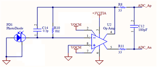
I designed a PCB board using the TMS320F28377D and I am using the built-in ADC with a differential input to have a 16-bit result. Currently, my circuit seems to work fine when I check my signals on the oscilloscope, but once I connect to the ADC inputs, the results (from the ADC) shows the signal as very noisy.

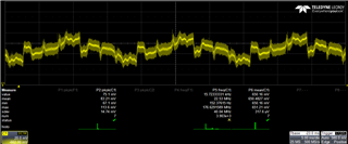
I decided to test the (16-bit) ADC using the LaunchXL-F28379D, and I notice the same thing happening. I applied a DC voltage to the ADC, and the ADC read the signal, but with +-50mV fluctuations. Where is this noise coming from, and how do I fix this?

Thank you.

  • Dyon,

    Can you describe the POS and NEG signals that you are forcing into the differential ADC inputs? The levels? How they are buffered?

    How is the ADC configured? Clock speed? ACQPS?

    Are you using a 3.0V VREF level on your board like the LaunchPad?

    It may help to see a series of consecutive samples.

    -Tommy

  • Tommy,

    This is currently my circuit design that I am feeding to the differential ADC inputs. 

    I am currently running the C2000Ware_3_04_00_00\driverlib\f2837xd\examples\cpu1\adc\adc_ex11_multiple_soc_epwm example on the LaunchXL-F28379D. I have the ACQPS set at 63 (as in the example) , the SYSCLK should be 200MHz, and the ADC clock prescaler is 4.

    The input levels should just be DC voltages. I have tried varying the input from 0-3.3V, but it always fluctuates +-50mV. (On the oscilloscope there are no fluctuations)

    Dyon

  • Dyon,

    I assume that you have modified the example to operate in 16-bit mode instead of 12-bit mode.

    When you observe the signal on the o-scope, are you only looking at the PD1 input? I recommend observing the differential ADC signals at R8 and R11 for a more accurate representation of what the ADC is sensing.

    Please report these voltages so that we can verify that they satisfy the datasheet requirements for 16-bit operation of the ADC.

    Please also observe these signals using high resolution time (ns range) and voltage scales (mv range) to see how quickly the signal buffering responds to the ADC sampling disturbance. AC coupling may be helpful if the DC offset is out of range.

    Are you monitoring the same result variable between ISR iterations or are you comparing two result variables against each other per ISR iteration?

    -Tommy

  • Tommy,

    Yes, I modified the example to operate in 16-bit mode. I also played around with the sampling rate, but it did not improve anything.

    When I look at the signals on the oscilloscope, I look at ADC_Ap and ADC_An. These are the differential signals going to the ADC. These two inputs will always be between 0V and 3.3V. I will try to collect some data from the oscilloscope and the ADC to share with you. 

    When I am monitoring the ADC result I am looking at the same result variable each time. I am looking at raw data read by the ADC. It does read the input levels correctly, but it has that noise attached to it. 

    Dyon

  • After more investigation, I figured out that what I am seeing on the oscilloscope is not "good" as I previously stated. I took a closer look, and it is definitely my circuit that's the cause of the problem. 

    This is the POS channel (ADC_Ap): 

    Any idea what in my circuit could be causing this?

  • Dyon,

    That output looks like a very regular and periodic complex waveform, as if it was being instigated by a repeating set of events.

    I would first see if the output is stable when the output buffer is not connected to anything. This will let you know if the issue is primarily from the buffer circuit itself, or if there is a dynamic interaction between the buffer and the board+device.

    If the board+device is contributing to the noise, I would keep an eye on the o-scope while methodically eliminating system activity/components to see if anything in particular is correlating with the noise:

    • ADC sampling
    • CPU activity
    • CCS/JTAG connectivity
    • Board connections
    • Power/Ground connections

    -Tommy

  • Tommy,

    I tried to go through the circuit piece by piece to try and figure out what component or system activity is causing the noise. I think I have determined that it has to do with the input side of the op amp. With a 1MOhm feedback resistor, the noise is about 5mVpp, with 2MOhm it is about 10mVpp, and with 3MOhm it is about 17mVpp. This seems to suggest I have 5nA of noise being added by the photodiode or the op amp. I am using a LTC1992 op amp, and will look more at the datasheet if I can determine where 5nA of noise is coming from.

    Dyon

  • Dyon,

    I am not an expert in this area, but noise that is proportional to resistor values reminds me of thermal noise that may then be amplified by the op-amp circuit.

    -Tommy