


Other Parts Discussed in Thread: CONTROLSUITE, C2000WARE
HI. I have big trouble HW setting in F28377D.
I finished setting up the ADC, PWM and CLA peripheral register.
I checked ADC starts of conversion at PWM count zero and at the EOC, adca1_isr function to be executed in a RAM section.
After that, I wanted to run a code standalone in the flash area without a debugger but there was a problem.
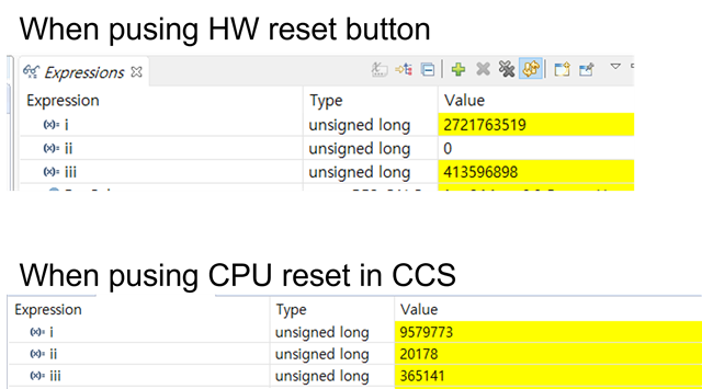
When I click CPU reset icon in the CCS debug window, PWM and ADC worked well
When I pushed HW reset button on my board(/XRS), PWM was well but ADC interrupt didn't work
I checked PWM output doing well from an oscilloscope.
I've touched a lot of the code to find the cause, but I haven't.
The variable 'i' is counter for main function, 'ii' is for adca1_isr interrupt and 'iii' is for CLA interrupt.
GPIO84, 72 are pulled up.
Please give me some advice.
Thanks
int main(void) {

	asm(" setc INTM");
	DINT;						// Clear all __interrupts and initialize PIE vector table:
	IER = 0x0000;				// Disable CPU __interrupts
	IFR = 0x0000;				// Disable CPU __interrupts and clear all CPU __interrupt flags:


	InitSysCtrl();				// Initialize System Control:
								// PLL, WatchDog, enable Peripheral Clocks
								// This example function is found in the F2837xD_SysCtrl.c file.

	InitGpio();					// Initialize GPIO:
								// This example function is found in the F2837xD_Gpio.c file and
								// illustrates how to set the GPIO to it's default state.

	InitPieCtrl();				// Initialize PIE:
								// InitPieCtrl - This function initializes the PIE control registers to a
								// known state.


	InitPieVectTable();			// Initialize the PIE vector table with pointers to the shell Interrupt
								// Service Routines (ISR).
								// This will populate the entire table, even if the interrupt
								// is not used in this example.  This is useful for debug purposes.
								// The shell ISR routines are found in F2837xD_DefaultIsr.c.
								// This function is found in F2837xD_PieVect.c.

	InitEQep();					//Initialize eQEP:

	InitCLA();					// Initialize CLA:

	ConfigureADC();				//Initialize ADC:

    InitEPwm();					// InitEPwm - Initialize EPWM configuration

    SetupADCEpwm();

	// Interrupts that are used in this example are re-mapped to ISR functions found within this file.
	EALLOW; 									// This is needed to write to EALLOW protected registers
	PieVectTable.ADCA1_INT = &adca1_isr; 		//function for ADCA interrupt 1
	PieVectTable.CLA1_1_INT = &cla1Isr1;		//function for CLA1 interrupt


//
// Enable global Interrupts and higher priority real-time debug events:
//
	IER |= M_INT1; 		//Enable group 1 interrupts
//	IER |= M_INT10;		//Enable group 10 interrupts
    IER |= M_INT11;		//Enable group 11 interrupts

	EINT;  // Enable Global interrupt INTM
	ERTM;  // Enable Global realtime interrupt DBGM

//
// enable PIE interrupt
//
	PieCtrlRegs.PIEIER1.bit.INTx1 = 1;		//for ADC_A INT1	this is high priority
	PieCtrlRegs.PIEIER11.bit.INTx1 = 1;		// Enable INT 11.1 in the PIE (CLA Task1)
	PieCtrlRegs.PIEIER11.bit.INTx8 = 1;		// Enable INT 11.8 in the PIE (CLA Task8)

	EDIS;   // This is needed to disable write to EALLOW protected registers

	ResPara.Amp = 0.8;
	ResPara.Freq = USER_RES_EXC_FREQ_kHz*1000.0;
	ResPara.n = 0;
	ResPara.Ts = USER_RES_PWM_PERIOD_sec;
	ResPara.Offset = 0.0;
	ResPara.Phase = 0.5;

	USER_PMW_Config.Freq_kHz = 10;
	USER_PMW_Config.Deadtime = Deadtime_1us;
	USER_PMW_Config.ADCsampling_CMPC = 72;

	for(;;)
	{
		i++;
		GpioDataRegs.GPASET.bit.GPIO24 = CLAflag.CalcStart;
		GpioDataRegs.GPACLEAR.bit.GPIO24 = CLAflag.CalcDone;

	}

	return 0;
}


//
// adca1_isr - Read ADC Buffer in ISR	(10kHz)
//
__interrupt void adca1_isr(void)
{
	GpioDataRegs.GPATOGGLE.bit.GPIO25 = 1;
	ii++;

	// toggle status LED
	if(++gLEDcnt >= (uint_least32_t)(USER_PMW_Config.Freq_kHz*1000.0 / LED_BLINK_FREQ_Hz))
	{
		GpioDataRegs.GPATOGGLE.bit.GPIO31 = 1;
		gLEDcnt = 0;
	}

    //
    // Check if overflow has occurred
    //
    while(AdcaRegs.ADCINTFLG.bit.ADCINT1 & AdcbRegs.ADCINTFLG.bit.ADCINT1 & AdccRegs.ADCINTFLG.bit.ADCINT1)	//wait ADC conversion process
    {
        AdcaRegs.ADCINTOVFCLR.bit.ADCINT1 = 1; //clear INT1 overflow flag
    	AdcbRegs.ADCINTOVFCLR.bit.ADCINT1 = 1; //clear INT1 overflow flag
    	AdccRegs.ADCINTOVFCLR.bit.ADCINT1 = 1; //clear INT1 overflow flag

        AdcaRegs.ADCINTFLGCLR.bit.ADCINT1 = 1; //clear INT1 flag
        AdcbRegs.ADCINTFLGCLR.bit.ADCINT1 = 1; //clear INT1 flag
        AdccRegs.ADCINTFLGCLR.bit.ADCINT1 = 1; //clear INT1 flag
    }

    CTRL_run();

    PieCtrlRegs.PIEACK.all = PIEACK_GROUP1;

    GpioDataRegs.GPATOGGLE.bit.GPIO25 = 1;

}
