This thread has been locked.

If you have a related question, please click the "Ask a related question" button in the top right corner. The newly created question will be automatically linked to this question.

TMS320F28388D: How to get stable and accuracy 16bit ADC result

Part Number: TMS320F28388D
Other Parts Discussed in Thread: C2000WARE, REF5025, REF6025, OPA350, THS4031, OPA320, OPA2320

Hi Expert 

Customer report the F28388 16bit ADC result is not accuracy and linearly enough. I try validate it as below:

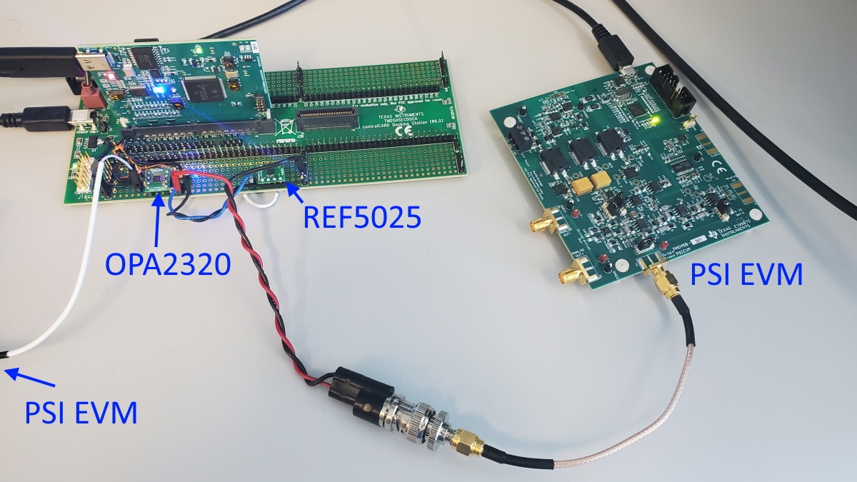
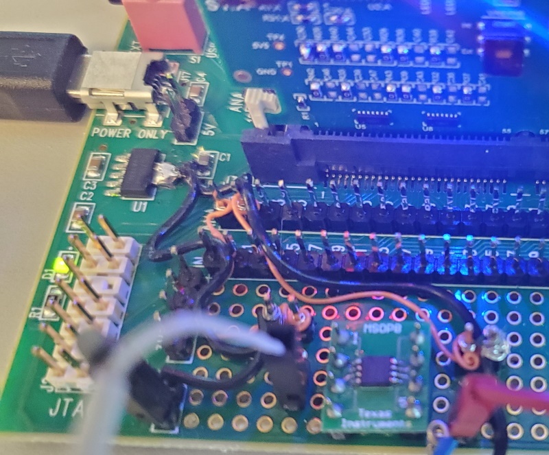
Hardware: F28388 control card + Experimenter Kits;   connect a 2.5V Battery +/- as signal source to ADCA pin A0 & pin GND in Experiment Kit  

Firmware : adc_ex2_soc_epwm from "C2000Ware_3_03_00_00\driverlib\f2838x\examples\c28x\adc";   with ADC_setMode(ADCA_BASE, ADC_RESOLUTION_16BIT, ADC_MODE_SINGLE_ENDED);

Result: real-time check the adcAResults[256] in CCS, and found the difference could up to 500 LSB between max and min value. I think it is much worse than ADC spec in datasheet.

May I get advice how we should setup the hardware and firmware to get stable and accuracy 16bit ADC result?

  • Hi Terry,

    A battery is really not a good signal source.  You need something that is (1) low noise and (2) low impedance and you need to be very careful of the physical construction and cabling of your source (even at 12B resolution).  

    Highly recommend that you pick up a Precision signal injector EVM: https://www.ti.com/tool/PSIEVM.  While this is primarily designed to supply an extremely clean 2kHz sine wave, it also does a pretty good job of providing a clean DC signal. The output is also reasonably buffered, so as long as you keep cabling very short and tidy, you might be able to get away with using this directly.  

    Another possible DC signal source would be something like REF5025 or REF6025.  You'd probably want to put an R-C filter at the output, which will help you get a low-noise signal (but maybe not low impedance).

    Either way, even nice and tidy routing with mostly shielded cables will have some inductive series impedance, so you likely will want to buffer the signal locally on the ControlCard using a low-noise and high bandwidth op-amp (say OPA350, OPA320, or THS4031).  You'll also want to populate the R-C components on the ADC input on the ControlCard (e.g. for F28388D ControlCard for channel A0 you might want to populate R51 and C32). 

    Some other resources that might help:

    Information on driving the ADC input correctly:

    https://training.ti.com/node/1139103 

    • Background info on ADC input driving

    https://www.ti.com/lit/an/spract6/spract6.pdf 

    • Explains how to determine proper R-C values and S+H time for the ADC input when using a high-bandwidth driving op-amp

    https://www.ti.com/lit/an/spracv0/spracv0.pdf 

    • Of particular interest is that if you drive the ADC input with something that has a large capacitive output (say REF5025 with a uF cap on the output) you may need to control the sample rate to prevent the signal source from drifting.  

    DIP Adapter EVM is great for building circuits (either REF or op-amp circuits) on the ControlCard protoboard area:

    https://www.ti.com/tool/DIP-ADAPTER-EVM

    And here are some pictures of a setup for doing DC codespread evaluation on a 12B ADC using ControlCard + PSI EVM + REF5025:

    • Right channel of OPA2320 uses either PSI EVM or REF5025 to supply DC value
    • Note that all routes have a ground return path (black wire) wrapped around the signal cable, even the route between REF5025 and the op-amp on the protoboard area.  This provides a similar functionality to the ground plane on a PCB.  

    This image shows a close up of the routes between the op-amp output and the ADC input pins.  Note again that I've provided a ground return path (black wires) to go with the signal wires (orange).  I've improvised a connection to ground at the output of U1 LDO since that was the closest place to connect to ground on the board near the ADC inputs.


  • Hi Devin

    Thanks your so much detail advice. 

    I have apply the PSIEVM and DIP-ADAPTER-EVM according your recommend, will setup test platform to re-verify ADC performance after receive kits.

    Since kit setup still need wait some time, if you already have been done test on C2000 16bit ADC, may I ask if you could help share test result special accuracy and linearly in difference voltage signal?

  • Hi Terry,

    Accuracy is comprised of gain error, offset error, and linearity error (INL/DNL).  All of these are specified as min/max values in the datasheet, so the customer should have pretty high confidence in these.  I don't have any bench data handy for linearity, accuracy, or DC codespread for F2838x 16B differential mode. 

    Can you describe the 'linearity' error they are seeing?  A good place to start for debug would be what circuits they are using to drive the ADC and what S+H they have set to correspond to these drivers.  If the input driver isn't appropriate, then you can get various errors.  See https://www.ti.com/lit/an/spract6/spract6.pdf  and https://www.ti.com/lit/an/spracv0/spracv0.pdf ; it is very highly recommended that they simulate their ADC driving circuits to ensure appropriate S+H settling.