Part Number: TMS320F28032
Hi Every one,
Board: F28032
The program is running in Flash, and periodically resets when running for a period of time, Can you provide a reference idea for the solution?
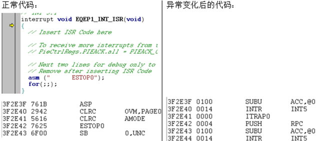
When connected to the emulator for single-step debugging, it is found that the Flash program enters an illegal interrupt.
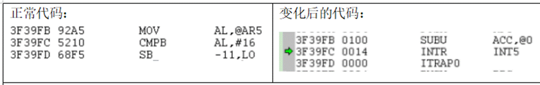
The normal operation is shown in Figure 1, and the actual code operation is shown in Figure 2.
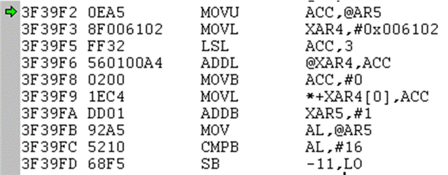
Fig.1
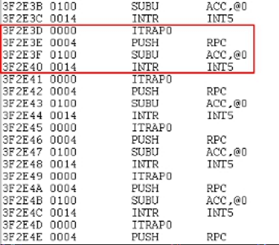
The next line of code of 3F39FB has changed from a normal code to an illegal interrupt code.
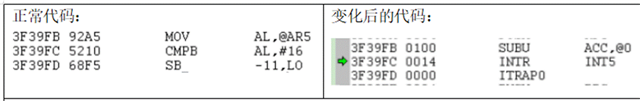
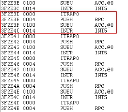
Fig.2
INT5 is not enabled in the program, but it calls INT5 during the illegal interrupt code, which causes unknown phenomena and risks.
So, Experts, have you encountered this situation before? From the software, there is a way to locate the cause ?