


Hi team,
The customer are debugging the BUILDLEVEL == LEVEL8 section of the HVPM_Enhanced_Sensorless project and here's some questions may need your help:
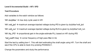
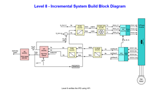
1. As described in doc in the HVPM_Enhanced_Sensorless project, in BUILDLEVEL == LEVEL8, after setting lsw to 1, the motor shaft can be rotated to observe the rotor position. If the observer parameters are correct, if the correct experimental phenomenon is: Hfi1.thetaEst outputs a triangle wave that changes with the rotor position.
2. After setting lsw to 1 as described in the document, hfi1.thetaEst is fixed to a value, but by turning the motor shaft, hfi1.thetaEst does not change with the motor rotor position and sometimes even oscillates. High frequency signals injected into the motor phase current can be observed. Is that the parameters of the hfi have not been adjusted properly? If so, what parameters need to be adjusted?
The program parameters are as follows:
#define INDEX_CNT 8
#define VOLT_PU(A) _IQ( A/(sqrt(3)*BASE_VOLTAGE) )
#define HFI_VOLT_RUN 7.6
#define HFI_VOLT_IPD 7.6
// HFI magnitude (duty cycle) parameters
hfi1.Kp_IPD = _IQ(8.0);
hfi1.Kp_RUN = _IQ(8.0);
hfi1.base_wTs = _IQ(200*T);
hfi1.Ts = _IQ(T);
hfi1.dutyMax = _IQ(0.8);
hfi1.volt_ipd = VOLT_PU(HFI_VOLT_IPD);
hfi1.volt_run = VOLT_PU(HFI_VOLT_RUN);
// HFI frequency (timing) parameters
hfi1.Squ_PRD_set = 1;
hfi1.HFI_Time1 = 400; //400
hfi1.HFI_Time2 = 450; //450
// Initialize HPF parameters
hpf_coeff1.freq = _IQ(25.0);
hpf_coeff1.PiT = _IQ(PI*T);
HPF_INIT(&hpf_coeff1);
// Initialize NS determination parameters
ns_id1.cntON = 1; // number of ON pulses within cntPRD below
ns_id1.cntPRD = 30; // pulse period per switching state
ns_id1.PWM_ch[0] = 1; // epwm1
ns_id1.PWM_ch[1] = 2; // epwm2
ns_id1.PWM_ch[2] = 3; // epwm3
ns_id1.PWM_PeriodMax = pwm_state.PeriodMax;
Could you help check this case? Thanks.
Best Regards,
Cherry
