


Part Number: TMS320F28030
Hello, TI's engineers!
I am debugging the HVPM_Enhanced_Sensorless_2803x project . I have encountered some problems in debugging process and hope to get your help.
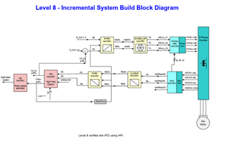
Q1: I have read the DOC documentation for the HVPM_Enhanced_Sensorless_2803x project, however, I can not understand the correct experimental phenomena for BUILD LEVEL 8 very well.
This is my understanding:After the variable lsw being set to 1, if I rotate the motor rotor, the variable hfi1.thetaEst will be changed with the position of the rotor, and a triangle wave should be output like the wave shown by position sensor of the motor.
However, when I rotated the motor rotor, the variable hfi1.thetaEst only fluctuated slightly, and would not change with the change of the motor rotor.
Is this a correct experimental phenomenon or my HFI parameter is not adjusted properly? If I am wrong, what is the correct experimental phenomenon?
Q2: If my HFI parameters are not adjusted properly, which parameters are supposed to adjust and how to adjust them?
The motor parameters:Motor_Poles=3,Motor_Rs=0.015Ω,Motor_Ld=0.000313H, Motor_Lq=0.000756H, Vdc=24V.
My program parameters are shown as follows:
#define VOLT_PU(A) _IQ( A/(sqrt(3)*BASE_VOLTAGE) ) // (sqrt(3)*BASE_VOLTAGE)=24V
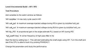
#define HFI_VOLT_RUN 3.0 /* Max duty cycle below this Vdc (in V) @run */
#define HFI_VOLT_IPD 4.0/* Max duty Cycle below this Vdc (in V) @ipd */
// HFI magnitude (duty cycle) parameters
Hfi1. Kp_IPD = _IQ (8.0);
Hfi1. Kp_RUN = _IQ (20.0);
hfi1.base_wTs = _IQ(200*T);
hfi1.Ts = _IQ(T);
Hfi1. DutyMax = _IQ (0.65);
hfi1.volt_ipd = VOLT_PU(HFI_VOLT_IPD);
hfi1.volt_run = VOLT_PU(HFI_VOLT_RUN);
// HFI frequency (timing) parameters
hfi1.Squ_PRD_set = 1; /* 16 IPD // 8 low speed for Bosch // 1 for E-bike */
hfi1.HFI_Time1 = 300; / / 400
hfi1.HFI_Time2 = 400; / / 450
// Initialize HPF parameters
Hpf_coeff1. Freq = _IQ (18.0);
hpf_coeff1.PiT = _IQ(PI*T);
HPF_INIT(&hpf_coeff1);
// Initialize NS determination parameters
ns_id1.cntON = 1; // number of ON pulses within cntPRD below
ns_id1.cntPRD = 30; // pulse period per switching state
ns_id1.PWM_ch[0] = 1; // epwm1
ns_id1.PWM_ch[1] = 2; // epwm2
ns_id1.PWM_ch[2] = 3; // epwm3
ns_id1.PWM_PeriodMax = pwm_state.PeriodMax;
Enclose some of the documents I have read.
Looking forward to your reply!
