


Part Number: TMS320F28335
hi. I want to implement space vector pwm to epwm module using Simulink. But need some clarification of some points.
I don't use any adc module. My Simulink blocks consist of Vabc signals (my desired signals), Alpha-beta transformation, Vref and phase angle block, modulation index block, and SV section selection block. My main problem is the scaling for the f28335 microcontroller. In literature, many examples are used with adc, they redesign blocks for adc module. They multiply with 2038 on the adc signals then use uint16 block etc.
My questions;
1-If did not use any adc and I create my desired signals with just simulink, do I need any adjustment on desired signals?
for adc example, voltage sensors that have a 100V maximum limit are used implementation. They work on 80V rms values. In the simulink they calculate desired signals amplitude 2048*80/100=1638. after then use some blocks like below
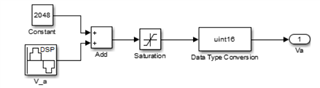
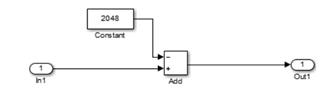 after these transformations, alpha-beta transformation and so on.
2- In the epwm blocks, can I add my switching freq values? Because I want to change switching frequency with time. For now, I design like below. svpwm signals go to directly epwm block after pwm scaling.

