This thread has been locked.

If you have a related question, please click the "Ask a related question" button in the top right corner. The newly created question will be automatically linked to this question.

LAUNCHXL-F28379D: how to implement space vector generator to ePWM module using Simulink ?

Part Number: LAUNCHXL-F28379D

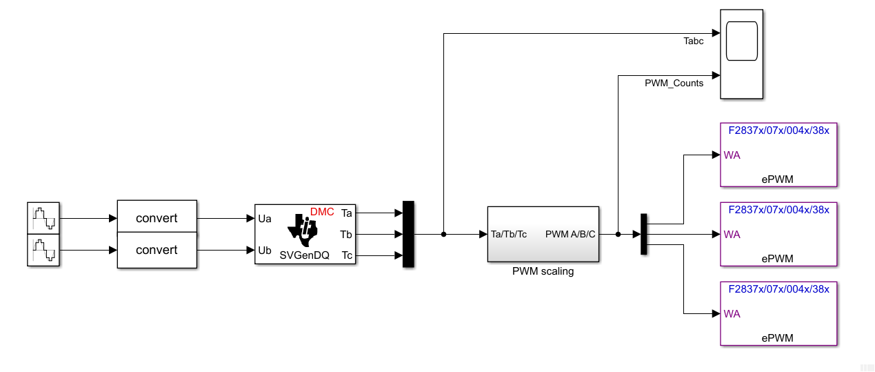
I'm having trouble producing PWM signal using Space Vector Generator DQ in Simulink.

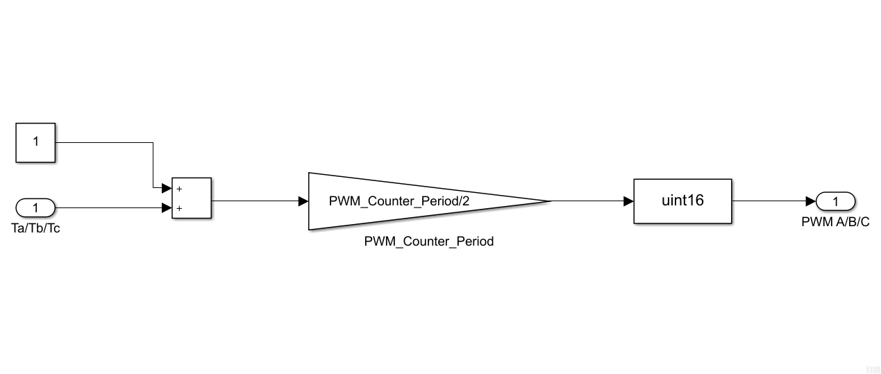
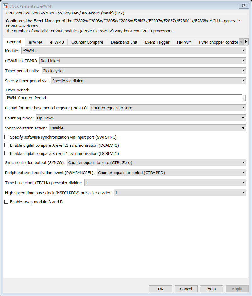
How should i set the ePWM Module parameter so that it can produce the right signal?

Please help.

Regards,

Andy

  • Hi Andy,

    To implement generation of correct PWM duty cycles, you’ll need to scale the 'Ta, Tb and Tc' outputs of SVGenDQ block to PWM Counter period. The ePWM block works with a timer count (e.g. For image below PWM_Counter_Period = 4 clock cycles)

    You may compute PWM_Counter_Period by using the following math:

    CPU_frequency = 200e6; %(Hz)

    PWM_frequency = 20e3; %(Hz)

    PWM_Counter_Period = CPU_frequency/PWM_frequency/2; %(PWM timer counts)


    An example is shown in the model below.


    This can also be accessed by the example model of the LaunchXL-F28379D by typing ‘c28379Dpmsmfocdual_cpu1_ert’ at your MATLAB command window. The required subsystem is present at following location in the model: ‘c28379Dpmsmfocdual_cpu1_ert/FOC Alogrithm Motor/Torque Control Algorithm/Generating Space Vectors’

    The PWM Scaling subsystem is shown below.

    Once you obtain the required PWM_Counts for generation of PWMs, you may configure the ePWM blocks to generate space vectors via multiple options, as shown below. Note that the timer period units are CPU clock cycles, which are used to obtain the required PWM time period.


    There are multiple events that can be configured to generate outputs. The image below illustrates CMPA and CMPB values (which are the PWM_Counts computed by you).

    Please note that, for the settings shown above, there are two possibilities for PWM generation – Active High & Active Low:

    • Active High: The MathWorks example under discussion uses ‘Active High’ PWM generation by configuring ‘Action when counter=CMPA on up-count’ = CLEAR, and ‘Action when counter=CMPA on down-count’ = SET. This results into 25% duty cycle for PWM_Counts = PWM_Counter_Period/4
    • Active Low: TI recommends ‘Active Low’ PWM generation by configuring ‘Action when counter=CMPA on up-count’ = SET, and ‘Action when counter=CMPA on down-count’ = CLEAR. This results into 75% duty cycle for PWM_Counts = PWM_Counter_Period/4.

    The above two configurations can result in 180’ out-of-phase generation of PWM voltages. Usually, these differences are compensated by PI controllers generating these voltages.

    The PWM counts corresponding to active duty cycles are fed via input port of ePWM block to the CMPA register of Counter Compare unit of the ePWM peripheral. These settings are shown below.


    Also, you can configure deadbands by following tab of the ePWM block. Note that we didn't feed any input to CMPB of Counter Compare, but this module would still generate PWMB (alongwith PWMA) due to the 'Active High Complimentary' settings for the deadband generation.

    For more details, pl refer to the following resources:

    1. https://www.mathworks.com/help/supportpkg/texasinstrumentsc2000/ref/c280xc2802xc2803xc2805xc2806xc2833xc2834xf28m3xf2807xf2837xdf2837xsf2838xf28004xepwm.html
    2. http://www.ti.com/lit/ug/sprug04a/sprug04a.pdf
    3. https://www.mathworks.com/matlabcentral/answers/438952-how-does-the-ti-c2000-epwm-block-work

    I hope this was helpful. 

    Have a good day!

    --

    Darshan Pandit | MathWorks

    For more resources see: MATLAB Central 

  • Hi Darshan,

    This is really helpful. I don't really understand the explanation in the TI file, but somehow you made it very simple and easy to understand,

    Thank you so much.

    Best,

    Andy