This thread has been locked.

If you have a related question, please click the "Ask a related question" button in the top right corner. The newly created question will be automatically linked to this question.

TMS320F28379D: SCI flash programming on custom made hardware

Part Number: TMS320F28379D
Other Parts Discussed in Thread: C2000WARE, UNIFLASH

Dear Team,

I am trying to burn/ flash the .hex file on the target board using c2Prog_v1.8.6 utility using SCI boot. I have set the boot select pins GPIO72 & GPIO84 to 1 & 0 respectively. I am using SCIA for flashing (GPOI28-Rx, GPIO29-Tx). Can anyone please help me with the correct and concise procedure to begin with. Do I need to make in special changes my code to achieve this? 

  • Pravin,

    For SCI boot, GPIO72 should be 0 and GPIO84 should be 1 (you did the other way - please check).

    Regarding the SCI used for flashing:  By default, the F2837x SCI bootloader uses GPIO84/85 for SCI boot communications.  If you instead want to use GPIO28/29 for SCI Boot, you need to program the BMODE bit-field of the BOOTCTRL register in OTP accordingly (details are available in TRM's boot chapter 4.9.6).  Also, you need to obtain a custom C2Prog configuration from Codeskin for that.  Please contact Codeskin directly at info@codeskin.com.

    Thanks and regards,
    Vamsi

  • Thanks Vamsi, for your reply. Yes, the state of bootpins was typo. Does TI have any utility which can be used to flash using SCIA pins without any special configurations (unlike Codeskin)? Also, OTP once programmed for SCIA boot, it can not be reprogrammed, right? FYI, I am using CCS7.

  • Update: I thought of trying out SCI boot process on F2837xD control card R1.3 with serial_flash_programmer.exe (located at C:\ti\c2000\C2000Ware_4_00_00_00\utilities\flash_programmers\serial_flash_programmer) for simplicity for both of us. Also, I have found well explained document to achieve this in the same folder. As, by default 

    the F2837x SCI bootloader uses GPIO84/85 for SCI boot communications.

    I understand that i need to use serial cable to connect the control card to my laptop. But, I don't see GPIO 84 available on control card docking station.....Please help me with the detailed connection diagram for flashing.

    Please answer my queries with simplest and finest details possible as its been just 5 days i am working with TI c2000 DSP and CCS7. 

    Thanks.

  • Pravin,

    Once programmed, OTP can't be modified again - you are correct.

    TI provides SCI flash kernels - please read this: https://www.ti.com/lit/sprabv4 

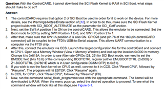
    Below snapshot is taken from this application note:

    Regarding the CCS version that you need to use, please take a look at: [FAQ] Product Change Notice (PCN) 20180523001.1 and PCN 20200115000.2 for TMS320F2837x and TMS320F2807x devices: https://e2e.ti.com/support/microcontrollers/c2000/f/171/t/729543?-FAQ-Product-Change-Notice-PCN-20180523001-1-for-TMS320F2837x-and-TMS320F2807x-devices

    Regarding your other questions, I will ask our kernel expert to help you.

    Thanks and regards,

    Vamsi

  • Pravin, 

    The controlCard will work with the flash kernel example by connecting the mini-USB cable to the A:J1 port. You do not need to attach anything to the pins on the docking station. Please follow the steps outlined in the flash kernel app note screenshot above to run the example on the controlCard. 

    Thanks,

    Anu

  • Thanks Vamsi & Anu for your reply.

    1. I have followed the procedure as mentioned in the document. but in command terminal my screen is stuck on-

    Usually, how much time kernel downloading takes?

    2. Also when i connect CPU1 in CCS7 and changes content of 0xD00 to 0x815A manually in memory window, it reflects in memory view. But, the content gets reset to 0x035A when I disconnect. Same thing happens with CPU 2.

    3. I feel that 1 is happening due to 2, correct? 

  • I am able to resolve above questions by reading other threads. I was following wrong steps in setting content of 0xD00 to 0x815A. However, I am not yet succeeded in SCI flashing, I have some doubts which i will ask subsequently as i progress further . Lets keep this thread open for now. You guys gave me much needed breakthrough. Thanks.

  • Pravin,

    Glad you were able to make progress, let us know when you have further questions.

    Anu

  • Anu,

    1. I am able to flash the CPU1 & CPU2 successfully with CPU1_FLASH_STANDALONE & CPU2_FLASH, respectively. But, always only LED from CPU1 is blinking & LED on CPU2 is continuous ON. I followed following threads, but that didn't gave me a solution.

    https://e2e.ti.com/support/microcontrollers/c2000-microcontrollers-group/c2000/f/c2000-microcontrollers-forum/724821/ccs-launchxl-f28379d-unable-to-make-cpu2-boot-from-flash-f28377d

    https://e2e.ti.com/support/microcontrollers/c2000-microcontrollers-group/c2000/f/c2000-microcontrollers-forum/925450/ccs-launchxl-f28379d-cpu2-not-booting-from-flash-after-reset

    I have upgraded to CCS9.2.0 & compiler 21.6.0.LTS. Any solution?

    2. Please guide me how can I change the BOOTCTRL value for SCIA boot in CCS7.0.0 & CCS9.2.0.

    3. Once BOOTCTRL value changed for SCIA boot, will TI XDS100V2 debug probe be working with the same device?

    4. I can use TI Uniflash utility for SCIA flashing (replacing Codeskin - C2Prog), correct?

  • Pravin, 

    Did you modify the linker command files for the blinky examples? The BOOTCTRL value change for the two CCS versions should be the same. The debug probe should still work with the device, you need to press reset in CCS after writing the BOOTCTRL values. I will check on the Uniflash question and get back to you. 

    Thanks

    Anu

  • Anu,

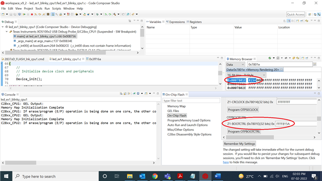
    1. No, I didn't modified linker command file. used as it is. Do I need to modify it? In addition to that I modified the value of Z1_BOOTCTRL (0x7801E) to 0x0000815A (to use SCI Boot mode). But after modification I am following below behavior:

    2. LED on CPU1 blinks (as expected) when CPU1_RAM and CPU1_FLASH is debugged trough TI XDS debug port. If I power reset the control card LED doesn't blink. Is it expected?

    3.Why program is not getting executed from FLASH memory?

    4. Also, I noted the value difference of values in CCS and memory map on location 0x7801E (encircled in image below), can you explain this please?

    5. I am able to do the SCI flashing with switch position 1,0 & 1,1 (through codeskin c2Prog utility); does it mean CPU1 is not coming out of GetMode boot?

    Please, help me with on priority basis. I am running out of time.

  • Pravin, 

    First, regarding the Uniflash question, you cannot use it for SCI flashing. 

    Regarding your other questions -

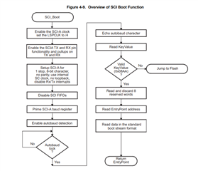
    If you intend on the device going to Flash after a reset, you need to program the OTP to go to Flash Boot - you currently have it set to SCI Boot. The SCI Boot Mode is used to download the flash kernel via the SCI Bootloader to RAM. The device is most likely going to the SCI bootloader, and that is why you are not seeing the example being executed from Flash. Since you cannot modify the OTP here, in order to get out of the SCI bootloader, you need to send it an incorrect key, any value other than 0x08AA - please refer to the screenshot below from the boot chapter of the F2837xD TRM:  

    Once you are in Flash, if the images have been programmed correctly, you will see the LEDs blinking. 

    I will ask the Codeskin expert to comment on your last question. 

    Thanks

    Anu

  • Dear Anu,

    1. Even I believe that DSP is in SCI boot mood always and not able to run code from flash. You have suggested to bring it to flash boot mode by sending an incorrect key. It can be done by editing the .txt file generated from .out file, correct?

    2. How can I change key when program is loaded through C2Prog utility.

    3. IMPORTANT Just to make things clear, let me put my task statement this way. Please confirm if I am following the right approach (as followed in this thread till now) to do it.

    Task: My service engineer should be able to update the firmware of F28378D through SCI interface (SCIA- pin no. 28 & 29) on field, using utility like C2Prog. Once updated and reset, f28379D should run the updated firmware through flash.

    4. If I am following wrong approach by any means, please correct me.

    Please involve codeskin expert in this thread ASAP, I am really running short of time. Also, provide contact details of support team in India for faster resolution.

  • Dear Anu/ Vamsi,

    Just to update you I have found answer to Q 1 in my last reply. Waiting for your reply on 2,3,4.

  • Pravin, 

    You can do the following - program Get Mode to Flash Boot, and use the default SCI pins if possible (84/85) - this way, you can just change the boot mode pins to SCI perform a firmware upgrade, and back to Flash Boot to run the application.

    If you wish to use the alternate SCI pins, you need to program Get Boot to SCI Boot with the alternate SCI pins - for this, you can contact Codeskin directly at info@codeskin.com to get a solution, and to answer your C2Prog questions. 

    Thanks

    Anu

  • Thanks Anu,

    If you wish to use the alternate SCI pins, you need to program Get Boot to SCI Boot with the alternate SCI pins - for this, you can contact Codeskin directly at info@codeskin.com to get a solution, and to answer your C2Prog questions. 

    Do you mean "Get Mode to SCI boot" here? Please confirm I have done the same by referring to previous thread posts.

  • Yes, you programmed Get Mode to SCI boot with the alternate pins in your previous replies, in the emulation registers and in OTP.

  • Ok. With this Get Mode to SCI boot I am able to flash control card using C2Prog utility (after modification in Z1_BOOTCTRL register) but unable to figure out how can I make F28379D to boot flash mode and run the flashed firmware? 

  • You would need to throw an incorrect key to the SCI bootloader upon reset as mentioned above. Codeskin can help with developing a solution for this, please reach out to them. 

    Thanks

    Anu

  • You would need to throw an incorrect key to the SCI bootloader upon reset as mentioned above

    Yes, this is applied for this particular control card in this discussion. But please revert on my following queries, considering I will be using the fresh devices (whose OTP is never modified in lifetime):

    1. Can you suggest alternate way (other than C2Prog) to load the firmware on F28379D using SCI pins 28 & 29 and then boot it from flash memory on fresh devices (whose OTP is never modified in lifetime)?

    2. I ALWAYS have to use GPIO84 & 85 for SCI flashing to achieve my task mentioned?

    3.

    You can do the following - program Get Mode to Flash Boot, and use the default SCI pins if possible (84/85) - this way, you can just change the boot mode pins to SCI perform a firmware upgrade, and back to Flash Boot to run the application.

    What if I have only pin SCI pins 28 & 29 accessible on my hardware?

    I understand, for Q3, i have to program Z1_BOOTCTRL with 0x815A but if I wont be able to run my firmware from flash after loading, then what is the use of it, just to copy the firmware to flash memory?

  • Pravin, 

    1. You could embed the flash kernel from C2000 into your application, and jump to it every time a FW update is needed - you would need to have some sort of host utility that would send the application the FW update signal - and then update the FW using pins 28 and 29. If you leave the OTP untouched and have both boot pins high, you will boot to Flash every time. 

    2. If you want to be able to just use the boot pins without using OTP to switch between SCI Boot and Flash Boot, then yes you need to use 84 and 85. 

    3. You can refer to the solution listed in #1. If you want to use the SCI bootloader with pins 28 and 29 via the boot pins, this is how you would need to do it. 

    Thanks

    Anu

  • Thank you for replies Anu,

    GPIO 84 is being used as boot select pin and SCITXD. So to be able to use it for SCI flashing (using codeskin) how I need to configure the pin no 84?

    Please give some reference circuit to follow.

  • Pravin, 

    I will get back to you in a couple of days. 

    Anu

  • Anu,

    Thank you for your solution, as this will require modification in hardware, it may take long. So request you to keep the thread open for any further queries.