This thread has been locked.

If you have a related question, please click the "Ask a related question" button in the top right corner. The newly created question will be automatically linked to this question.

TMS320F28379D: TMS320F28379D and ADC VREFHIx

Part Number: TMS320F28379D
Other Parts Discussed in Thread: OPA350, OPA365

Hi all, 

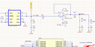
I'm using the TMS320F28379D but only plan to use two ADC channels (A and C). The user guide states that a buffer op amp is necessary, so I selected the MCP651 since it's cheaper than the OPA350 recommended by TI. I attached my schematic below. I have a 3.3V 0.1% accuracy reference that's buffered by the MCP651 and then finally to the 1uF with series resistance recommended by TI for 12 bit operation. 

  1. Why do I need a high frequency op amp here? Why can't I choose a cheaper, low-drift, high dc performance op amp to buffer the reference?
  2. Is the MCP621 okay here? That user guide says OPA350/OPA365 or similar, but I want the cost of the op amp to be <$2.
  3. What is the load at VREF that needs an op amp here to buffer? Is it the DAC? I just want to be clear on the purpose of the op amp.

Thanks so much,

Jimmy

P.S. I had a look at the following link, but still have the questions listed above.

e2e.ti.com/.../replacement-for-opa350-as-reference-buffer-for-adc

  • Jimmy,

    From the DS perspective of the F2837x device the requirement we give is for the 1uF cap(for 12-bit mode) on each VREF for stability reasons as the reference is switching in/out of the various internal cap arrays during a conversion for stability.  This gives rise to the need for an op-amp since most(all?) high accuracy references can't drive this kind of capacitive load.

    So on to the op-amp, when we picked the OPA350 we were looking for something high BW, low noise, and supported unity gain.  The series resistance is there to stabilize the output driving the cap load, and this will be specific to the op-amp characteristic/datasheet.

    All this to say the MCP651 looks good from a requirements POV from the C2000 team.  The only concerns we have is that:

    1)the 10Ohm in series is likely not needed(that is the role of the 0.1Ohm in series with the cap)

    2)The 0.1Ohm will need to be re-evaluated based on the cap and op-amp.  I think the 0.1 was for the higher 22uF cap used for 16-bit mode in our reference kits.

    Microchip should have some simulation/tables that can help arrive at the right numbers here.

    There is also a current requirement from(130uA 12-bit -190uA 16-bit), but that will not really be an issue in any case.

    Below are some videos from our precision labs team talking about the stability aspects I mentioned above, I think these may be helpful.

    TI Precision Labs series to understand simulation methodology:  https://training.ti.com/node/1139107

    TI Precision Labs op-amp stability videos: https://training.ti.com/node/1138805

    Best,

    Matthew

  • Jimmy,

    Also wanted to point out/caution on using a 3.3V reference, there is a requirement in the DS on keeping VREFHI < VDDA per below(also the other ADC inputs):

    Best,

    Matthew

  • Thanks Matthew,

    I wasn't aware about VREFHI<VDDA. I will try to lower VREFHI a little. 

    For the ADC inputs, most of my signals going into the ADC are limited by op amps (single supply powered by 3.3V). The op amps should saturate, which prevents the excess voltage. If a signal isn't buffered by an op amp, I have clamping diodes. The voltage may exceed 3.3V due to Vfwd of the diode, but I was using an absolute max of 4.6V (shown below). I think it's okay since any input >3.3V would indicate a fault condition any way and our system would shut down. I would like to avoid damaging the TMS though. Does that sound suitable?

    Best,

    Jimmy

  • Thanks Matthew, very helpful. 

  • Jimmy,

    You should be fine in terms of not damaging the device, the advice in the DS is more to avoid out of spec performance of the analog system on the device. 

    We have ESD diodes in place as well that will begin to turn on that activate the clamping current you see in the table you attached as well. 

    I think the 0.3V is to safeguard as even though not fully conducting things will begin to bias in the 0.3V to 0.7V range and start to influence things.

    Best,

    Matthew