Other Parts Discussed in Thread: C2000WARE
Hello,
I notice an issue with C2000 not behaving like ARM type CPU inside interrupt handlers. Seemingly race to instruction prefetch execution prior to termination by ( } ) syntax. The C++ compiler eabi.lib versions do not have this issue with ARM CPU only noticed in C2000. Perhaps the legacy COFF output format with TI v18.12.2.LTS has something to do with this odd CPU behavior?
Mostly noticed (for) and (while) loops process outside the functions last return and during increment count execution sequence. That is not proper behavior for next function to execute prior in either loop in clause variable count shown below. The loops shown below must complete prior to executing the outside and next function.
volatile uint32_t timeWaitCnt = 0;
/* Wait for a while */
while(timeWaitCnt < 500000)
{
timeWaitCnt++;
}
/* Executes this function inside (while) loop */
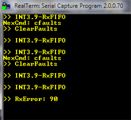
SCIprintf(">>Text Output \n");
//2nd example:
for(timeWaitCnt=0;timeWaitCnt < 500000;timeWaitCnt++)
{
}
/* Executes this function inside (for) loop */
SCIprintf(">>Text Output \n");
//3rd Example:
/* Wait 200ms */
SysCtl_delay(100000000 / 5);
//
SCIprintf(">> EntersFunction \n");