This thread has been locked.

If you have a related question, please click the "Ask a related question" button in the top right corner. The newly created question will be automatically linked to this question.

TMS320F28379D: Can I change ePWM up-down counting direction online?

Part Number: TMS320F28379D
Other Parts Discussed in Thread: TMDSDOCK28379D

Is it possible to change ePWM counting direction from up-down to down-up online, every half of the fundamental period?

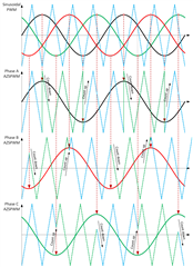
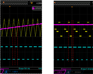
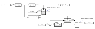
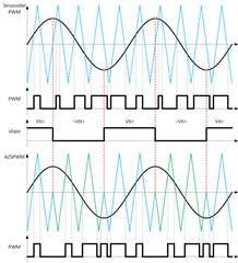
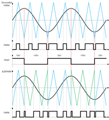
I would like to implement the AZSPWM method. To get the PWM signals, the following algorithm is used: If the slope of the reference phase voltage is positive then the modulating waveform is compared with Vtri and if the slope of the reference phase voltage is negative then the modulating waveform is compared with -Vtri.

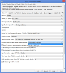
In MATLAB Simulink for ePWM block help file says I can set 'Counting direction after phase synchronization' if I select 'Set counter to phase value specified via input port' which creates a phase input port, PHS, on the block.

Further, in the help file, it says:

Counting direction after phase synchronization — Counter direction after phase synchronization
Count down after sync (default) | Count up after sync

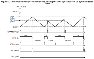
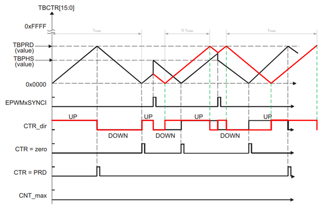
Configure the timer to count up or down, following synchronization. This parameter corresponds to the phase direction (PHSDIR) field of the Time-base Control Register (TBCTL).
Dependencies

This parameter appears when Counting mode is Up-Down and Synchronization action is Set counter to phase value specified via dialog or Input port.

PHS looks like a logical input? Is this correct? For the AZSPWM algorthm, the idea is to generate a logical signal (slope) for each ePWM based on the PWM reference slope, e.g. TRUE = rising slope, use Up-Down (Vtri) and FALSE = falling slope, use Down-Up (-Vtri).

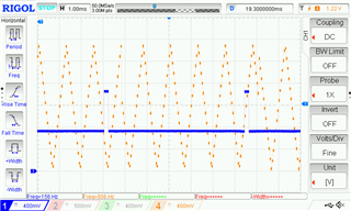
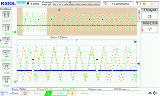
Fig 1: fsw = 5 * f0, Fig 2: fsw = 4 * f0


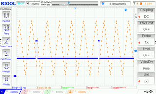
Edit: direction change can happen anywhere on the counting waveform; it all depends on when the slope change is detected.

So far in my ePWM blocks, 'Syncronisation action' is set to 'Disable'.

  • Hi,

    We are looking into this and will get back to you tomorrow.

    Thanks & Regards,

    Santosh

  • Hi,

    So far in my ePWM blocks, 'Syncronisation action' is set to 'Disable'.

    In this case counter direction change will not apply.

    I am not familiar with Simulink model, and may need to post the question on MathWorks forum for help.

  • Hi Santosh,

    thank you for the reply.

    After bit more reading, the ePWM Reference Guide Figure 12 and 13 show something really similar to what I'm looking for: a ramp direction changes on EPWMxSYNCI pulse. I could feed EPWMxSYNCI pulse on every slope change. It also seems that TBPHS (value) has to be set to half of TBPRD (value).

    The last value of the ramp before a direction change (Vtri(end)) + The first value of the ramp after direction change (-Vtri(0)) must be equal to TBPRD (value). I have shown two examples in my initial post for different switching frequencies.

    Are there any other techniques how to implement the algorithm?

    Before running the converter, are there any pins where I can see ePWM ramp signals and test the settings? I am using TMDSDOCK28379D for development.

    The reference guide is for TMS320x2834x. not for ePWx2837x (F28379D).

  • Did not get a chance to look at it. I will get back to you tomorrow.

  • Hi Santosh, did you have a chance to look at this? Do you maybe know what should be the settings for ePWM block to achieve AZSPWM pulse pattern?

  • Hi Mike,

    Sorry, I missed this. I will look at it and get back to you later today.

    Thanks & Regards,

    Santosh

  • Hi Santosh, do you have any updates on how to get a switching pattern for AZSPWM or NSPWM methods?

    Kind regards.

  • Hi Mike,

    I will get back to you on Monday. I need to check with ePWM expert.

    Thanks & Regards,

    Santosh

  • Hi Mike,

    If you want to change the direction in which the counter is counting then you could do this using the PHSDIR bit of the TBCTL register. You'll have to enable synchronization though and probably do a software synchronization pulse so when you detect the direction needs to change you can set the PHSDIR to the correct setting and then force a software sync. 

    Before running the converter, are there any pins where I can see ePWM ramp signals and test the settings? I am using TMDSDOCK28379D for development.

    One easy way to do this is to monitor the TBCTR value within the expression window of CCS. You can see the change in the time-base counter. 

    I'll loop in others who could suggest another method potentially. 

    Best Regards,

    Marlyn

  • Hi Marlyn,

    thank you very much for the reply.

    I have looked at PHSDIR signal and examples in ePWM Reference Guide Figure 12 and 13 and it seems this could be the solution. However, on a closer look I noticed that when the ramp change signal appears, the ramp starts counting from the pre-defined TBPHS (value).

    As I understood the AZSPWM and NSPWM algorithm says it should invert the ramp, i.e. start counting up (or down) from the last counter value before the direction change. and keep the same TPWM. I have added markups (in red) on the Figures 12 below to try to illustrate that. Is this possible to achieve? 

  • Hi Mike, 

    Yes this should still be possible. When you want to change directions you can read the TBCTR value, write that value to TBPHS, and then perform a software sync. You may have to increase the TBPHS value by one or two counts to account for the time to execute the write to TBPHS and the software sync. 

    Best Regards,

    Marlyn

  • Hi Marlyn,

    thank you again for the reply. I think I have a general idea of how to implement the algorithm and add +1 at the ramp direction change.

    Can this be done in MATLAB Simulink using C2000 ePWM block for F28379D? I am using MATLAB Simulink for writing application code.

    Looking at the ePWM block "Counting direction after phase synchronization" parameter, it looks like it is hard-coded, but in AZSPWM algorithm the ramp alternates direction on the slope change, i.e. Synchronization Event, as shown in the figure. Can the PHSDIR be changed online?

    Also, there is an "Enable counter capture" option. I assume this is to get the current value of TBCTR? Do you maybe know where is that option in Simulink ePWM block settings? Do I have to enable any other parameter before this is shown?

    Kind regards

  • Hi Mike,

    For MathWorks Simulink help, please take a look at MathWorks FAQ at this link below:

    If you have further questions, the best way to get support on MathWorks products is to contact MathWorks live tech support.

    You can also search for answers or post a question on MATLAB Answers C2000 forum. Additionally, there is info on MathWorks support C2000 in Documentation and Examples.

    I will close the thread from here as the software is supported by MathWorks team on their forum.

    Thanks & Regards,

    Santosh

  • Hi Santosh,

    Thank you for the advice. I did not find any posts on modifying existing C2000 blocks in Simulink, so I have posted a question to the MATLAB Answers C2000 forum. I am just putting it here for reference.

  • Sure Mike!!

    We do not have resource to support Simulink questions, so we rely MathWorks engineer's expertise. 

    Let us know when your issues are resolved.

  • Hi Marlyn,

    following steps from this thread, I was able to read TBCTR value, but the signal resolution highly depends on the task's sample time. So for higher switching frequencies, the triangle signals changes in bigger discrete steeps. If I try to increase sample time, I get overrun issues.

    For higher switching frequencies, a PWM pulse width does not correspond to a reference and triangle crossing point. I assume for a PWM pulse calculation, a TBCTR signal is more "detailed". Where is this done and is it possible to add the algorithm code to that "hidden" faster processor task?

    Kind regards

  • Mike,

    I am not sure if Marlyn has a chance to look at it. I will sync with Marlyn later today. Please expect response by Monday.

    Thanks & Regards,

    Santosh

  • Hi Mike,

    For higher switching frequencies, a PWM pulse width does not correspond to a reference and triangle crossing point. I assume for a PWM pulse calculation, a TBCTR signal is more "detailed". Where is this done and is it possible to add the algorithm code to that "hidden" faster processor task?

    Sorry, I didn't get your question. Are you talking about changing the PWM configuration in the ISR? can you please elaborate your question? 

    Regards,

    Chen

  • Hi Chen,

    I apologise for now being clear. In the figure on the left, I am recording a TBCTR with an 800 Hz switching frequency. It can be seen that the pulse width corresponds to the intersection of the reference and triangle (switching) signal. In the figure on the right, the switching frequency is 8,000 Hz. In this case, the pulse width does not match the reference and triangle intersection as shown on DACs (DACs' sample time is the same as the task's sample time).

    I understand this is related to the task's sample time and if I were to increase my task sample time by e.g., 10 times, I would get the same figure as on the fight, i.e., pulse width would correspond to the intersection of the reference and triangle signal. However, if I increase a task's sample time, I get over-run issues.

    To implement the algorithm suggested in this thread, I would need to use a high sample time task. By comparing PWM pulses for 800 Hz and 8,000 Hz I concluded that the PWM signal is calculated somewhere else, on some other really fast task.

    Is it possible to implement the algorithm for changing the up-down counter on that faster task? On the task I am using, the sample time is too low to get the algorithm working properly.

    Kind regards.

  • Hi mike,

    For the algorithm you mentioned, can you just create an isr when the direction of the sine wave changes. And inside ISR, you can use the software to trigger a sync signal to change the TBCTR value and the direction. 

    Regards,

    Chen

  • Hi Chen,

    thank you for the suggestion.

    I could use a software interrupt block to trigger a hardware interrupt in software and then set a hardware interrupt block to the same CPU and Peripheral Interrupt Expansion (PIE) numbers.

    Can I use any combination of CPU and PIE for a software interrupt, e.g., [1 1]? The table below shows this combination corresponds to the event coming from the ADCA1 module (i.e. hardware). And since I am using this ADCA1 input already, I might get a false trigger. Are there any (spare or non-active) CPU and PIE combinations which I can use without interference from a hardware trigger, i.e., a corresponding signal that will never go high, so I can overwrite that signal with a software trigger?

    Kind regards

  • Hi,

    Not sure if your sine wave frequency will change or not, if not, you can use the EPWM(same frequency with sine wave) to trigger the interrupt. The isr is not nested if you don't set it up. 

    Regards,

    Chen

  • Hi Chen,

    I have tried to implement the logic as suggested. When the slope change is detected, the counter value (ePMW's TBCTR) is recorded and if the slope is rising there is no change to phase offset and TBPHS = TBCTR, and if the slope is falling TBPHS = TBPRD - TBCTR (180 Deg shift).

       CounterShift_R2018a_v000.zip

    What I noticed is that the accuracy depends on my application sample time. In some cases counter slope change (Ch4) is correspond to slope change digital signal (Ch1), and in other cases, it is shifted for several periods.

    Even in some cases, sections are not shifted by 180 Deg:

    Is this possible to implement on some faster ePWM task? Is there any other approach I could try?

    This example is done for a switching frequency of 800 Hz. For 50 μs task's sample time, this gives 25 points per switching frequency period (counter). If I go to any higher frequencies, e.g., 8 kHz, the application would read only 2.5 points for each switching frequency period (counter), which is too little for the algorithm at the current sample time to work properly.

    Kind regards