This thread has been locked.

If you have a related question, please click the "Ask a related question" button in the top right corner. The newly created question will be automatically linked to this question.

TMS320F280049C: Tformat encoder can't work on F280049C

Part Number: TMS320F280049C
Other Parts Discussed in Thread: LAUNCHXL-F280049C, C2000WARE, LAUNCHXL-F280039C, BOOSTXL-POSMGR, SYSCONFIG

Hi expert,

Tformat's code does not run successfully on F280049C.
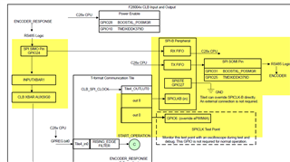
I used SPIA and connected PWM4B (GPIO7) to SPIA_CLK (GPIO56).
The TFORMAT_FREQ_DIVIDER in tformat.h is changed to 10.
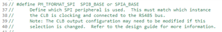
PM_TFORMAT_SPI in PM_tformat_Include.h is modified to SPIA_BASE.

When the program is running, the clock signal is always high and the TxEn signal is always low. And the program stops at 'while(tformatData.dataReady ! = 1) {}'

Can you tell me what could be the problem in this?

Regards,

Sibo

  • Hi Sibo,

    The subject matter expert will get back to you by tomorrow.

    Thanks & Regards,

    Santosh

  • I found that the CLB registers are not being written correctly. And I can't write manually.

  • Hi,

    Looks like CLB is not being configured in your case. Can you check if the clock is enabled to the CLB?

    Have you made any changes to the tformat example?
    Can you run the example as it is and check CLB is accessible and being loaded by s/w?

  • Hi,

    Thank you for your reply.I still can't solve this problem.

    Looks like CLB is not being configured in your case. Can you check if the clock is enabled to the CLB?

    I'm sure that the CLB clock is enable.

    Have you made any changes to the tformat example?

    I used SPIA instead,and modified some of the GPIO to fit the F280049C.No change was made to the CLB. 

    Can you run the example as it is and check CLB is accessible and being loaded by s/w?

    I have tried other CLB examples.They all do not work properly.The reason is the same.The CLB registers are not being written correctly.I did not make any changes to these examples.This is very confusing to me.

  • Hi,

    I have tried other CLB examples.They all do not work properly.The reason is the same.The CLB registers are not being written correctly.I did not make any changes to these examples.This is very confusing to me.

    This is not expected behavior. Are even able to write to the CLB registers through the debug window?

  • Hi,

    I can’t  write to the CLB register through the debug window. And I can write to other registers normally. 

  • Hi,

    It is worth mentioning that I am using a board designed by my company and not the LAUNCHXL-F280049C. is it possible that there is a circuit error causing this problem?

  • Hi, It seems like the CLB is not getting programmed for some reason. when you run the example code are the CLB registers being programmed?

  • Hi,

    The CLB register can’t be programmed when I am running any CLB example code. By the way,this problem is on the board designed by my company. I can run well on LAUCHXL-280049C. 

  • Hi, Thanks for confirming that the function works on LAUCHXL-280049C. Since the issue is in your hardware, I suggest you check the clocking - oscillator frequency if possible monitor the clock on the device using XCLKOUT signal. 

    Also, on your hardware, are you using the same part number? make sure you are using a CLB enabled part.

  • Hi, I checked XCLKOUT signal.There is no problem with it.

    I think if the clock is wrong,other functions can also be problematic.But now only the CLB register cannot be written, all other registers are functioning normally.

    Also, on your hardware, are you using the same part number? make sure you are using a CLB enabled part.

    I don't quite understand what you mean. does the F280049C exist as a model without CLB functionality?

  • I don't quite understand what you mean. does the F280049C exist as a model without CLB functionality?

    Hello,  

    The F280045 part does not have the CLB.  Bharathi's question is to check to make sure you are not using this part. 

    -Lori

  • Hi,

    Thank you for your reply. I’m sure that I’m using F280049C. 

  • Thank you for confirming. Let me summarize my understanding:

    1. Basic CLB examples (C:\ti\c2000\C2000Ware<version>driverlib\f28004x\examples\clb.  work on the LAUNCHXL but do not work on your custom board.
    2. The CPU doesn't seem to be able to write to CLB registers on the custom board. 
    3. All other registers / functionality seems fine on the custom board.
    4. XCLKOUT looks correct on the custom board.

    My next suggestion would be to make sure the clock is enabled to the CLB. Item (1) indicates this is not the problem, though.  If it was, both boards would show the problem. 

  • Hi,

    I tried using an external crystal and replacing the emulator and computer. But none of them could solve the problem.
    By the way, I would like to correct a previous message. The demo board I am using is F280039C. the example used is also the F280039 example. But even so, I don't think the CLB example of F280049C could be a problem. Please confirm this for me if it's convenient, thanks!

  • Thank you for the update, Sibo.

    To summarize - 

    1. You have a working board from TI.  A custom board shows the issue.
    2. Basic CLB examples (C:\ti\c2000\C2000Ware<version>driverlib\f28003x\examples\clb.  work on the TI board but do not work on your custom board.
    3. The CPU doesn't seem to be able to write to CLB registers on the custom board. 
    4. All other registers / functionality seems fine on the custom board.
    5. XCLKOUT looks correct on the custom board.

    Please confirm if I've understood the points correctly.

    The basic CLB examples in C2000Ware configure everything properly for the specific device. This includes turning on any clocks - there was an enhancement that provided the CLB with it's own clock enable. Double check that you have used a F28003x example.

  • Basic CLB examples (C:\ti\c2000\C2000Ware<version>driverlib\f28003x\examples\clb.  work on the TI board but do not work on your custom board.

    Hi,

    F28003x CLB example works well on TI board. 
    F28004x CLB example has problem on custom board.

    (Because I don’t have a LAUNCHXL-F280049C. I used LAUNCHXL-F280039C instead of it. )

  • Hi,

    The other points are correct.

    And here is a picture of the CLB register when running the example.

  • Hi Sibo,

    What is XDS100v3 emulator? Note worthy LaunchXL-39c has XDS110 emulator. The LaunchXL-49c has XDS110 emulator and have seen issues with newer TI-MCU class, DAP could not be unlocked via XDS100v1 CCS debug but XDS110 could. Wondering if XDS100v3 emulator is CLB dumb, does not have the GEL address support to access CLB registers in CCS debug.

    Can you use the LaunchXL-x39c XDS110 set jumpers for external JTAG header connect your custom board JTAG header and check if that is the cause of CLB issues. The newer JTAG XDS110 uses the two wire emulation mode set in the XDS configuration tab.

    Regards,

  • Hi,

    Thank you for your reply. That is a very useful suggestion. I never thought about the emulator version having these effects. I will try it tomorrow.

  • Thank you for the input, GI.  Looking forward to what you find, Sibo.  You may want to also try the latest Code Composter Studio (https://www.ti.com/tool/CCSTUDIO) if you are not already using it. 

  • Hello Sibo,

    An update to the T-Format example has been released in the motor control SDK 4.01.00.00. This includes ports to F28003x and F28004x as well as optimizations. 

    The release has a SW guide: 

    An update to the Design Guide will be posted by Wednesday. (www.ti.com/lit/TIDUE74)

    Regards

    Lori

  • Hi,

    Thank you for the information, it was very useful for me. I'm still trying to fix the CLB issue. Replacing the emulator didn't work. My colleague and I are trying to confirm if the chip might be damaged.

  • Hi,

    Could you please explain the GEL address in detail? And I would like to know if the two-wire and four-wire modes of JTAG have any effect on CLB. Thank you very much!

  • Hi Sibo Chen,

    Are you certain the CLB base address is being passed into the call prior to the break point? Perhaps the problem is not occurring at the break point set it further back and remove any speed or register optimizations to zero. If that helps debug register stepping slowly increase optimizations for each compile time, clean the project run debug util the CLB registers appear to lose data again, AKA backtracking optimization bugs.

    The GEL file is part of the debug simulator register address access in CCS debug. XDS100 emulator control is slower even v3 but check the project build MCU target exactly matches the custom PCB MCU class. When you done did x39 XDS110 emulator did you change the project target XML file to match and set 2 wire JTAG is advanced properties? Perhaps 2 wire JTAG may be the only way to access CLB registers being a more advanced architecture. The x39 JTAG emulator 2 wire debug is more like SWD, not sure XDS100 can do 2 wire debug TWD, seemingly not.

    BTW you can view even edit the MCU class GEL file in debug under XDS tools or around that area. Been awhile since I been there done did that Nerd. Can also find several GEL files under CCS install path emulators or simulators folder.

  • Sibo, 

    GEL files are documented in the Code Composer Studio (CCS) User's Guide here: https://software-dl.ti.com/ccs/esd/documents/users_guide_12.0.0/ccs_debug-gel.html

    The addresses that setup the memory map in the GEL file basically tell CCS about the device, what memory is RAM, what is Flash etc.  

    Using two-wire vs 4 wire on F28004x JTAG doesn't impact the peripherals available on the device. 

    Regards

    Lori

  • Hello, Sibo - were you able to resolve the issue?

  • Hi,

    Thank you for your help!


    The reason why the CLB register cannot be written is found. Because the chip we purchased was damaged for some reason. After replacing it with a new one, the CLB register can be written normally, and the CLB example can work normally.


    I am debugging the latest F280049C example. I changed the SPIB in the example to SPIA.
    The program is not working properly on the custom board.
    When running without BOOSTXL-POSMGR on LAUNCHXL-280049C, the
    The clock signal and TxEn signal are shown in the figure. There is only a very short pulse when the program is just running. Is this normal?

    GPIO6(CLK)GPIO7(TxEn)

  • Hi,

    I didn't find the information in desing guide.Could you please tell me how to modified the CLB output configuration if I want to use SPIA?

    Thank you very much!

  • CLB output configuration if I want to use SPIA?

    Refer to the F28004x CLB Input/Output diagram.

    You will need to change the connections related to the SPI. For Tile4_OUTLUT0 --> SPICLKB, this may require a change in tile. The technical reference manual will show the detail for which tile can access which peripheral directly. The alternative is to route this signal to the SPI clock on your board instead. 

    The configuration for routing and the CLB is done in the Library (CLB Tool) and in the example project's SysConfig.  The C2000 Academy has more information:

    https://dev.ti.com/tirex/explore/node?node=A__AEF1DyHUWKq1HXYGnpllKg__c2000Academy__jEBbtmC__LATEST

    See

    • "Getting Started" Module 1 for SysConfig information
    • "Advanced Topics" Module 9 for the CLB Tool information