This thread has been locked.
If you have a related question, please click the "Ask a related question" button in the top right corner. The newly created question will be automatically linked to this question.
Hello, i have a similar problem to this thread.
I have the same set: LAUNCHXL-F28379D, two BOOSTXL-DRV8305EVM's, and a 2MTR-DYNO.
I started working on the project in the title (and in the other thread) with the following voltage supply connected to the DRV8305's:
MEAN WELL
Model: UHP 1000 - 36
Output: 36V 19.6A
Jumpers JP1-JP5 are not populated, JP6 is populated, as the project suggested.
I followed the first steps (set MOTOR1_DRV and MOTOR2_DRV to DRV8305; Rebuild; Debug; CPU reset; Restart; Enable Real Time Mode; Resume; Set EnableFlag to 1).
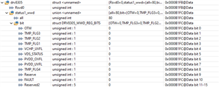
While running the projekt (on Build Level 1), it stays in the loop below (FCL_SFRA_XL_DualServo.c)
#elif (MOTOR1_DRV == DRV8305) InitDRV8305Regs(&motor1, DRV1_GAIN); // motor1.drv8305.cntrl7_gd.bit.PWM_MODE = drv8305_PWM_mode_6; InitDRV8305(&motor1); while (motor1.drv8305.DRV_fault) ; // hang on if drv init is faulty #endif
because i have these error flaggs set (PVDD_OVFL, VCHP_UVFL):
The voltage supply is not adjustable, so the solution from the other thread is not an option (for now).
Also the DRV8035's supply voltage ranges from 4.4V to 45V, so 36V supply should be fine. Am i mssing something?
I would be thankful for any clue.
Which project are you using? Please check if you install the BOOSTXL-DRV8305EVM on the LAUNCHXL-F28379D correctly.
Don't connect the motor to the DRV board in build level 1 and the maximum input voltage for BOOSTXL-DRV8305EVM is 21V.
Thanks for the fast reply!
Im using the project "FCL_379XL" of ControlSUITE with this documentation: Dual Motor Control Using FCL and Performance Analysis
Using SFRA on TMS320F28379D LaunchPad
I installed the DRV8305EVM's as the documentation shows in figure 6 and the motors are disconnected.
Oh okay, i'll try a lower voltage supply, but where are the 21V from? The BOOSTXL-DRV8305EVM User’s Guide says 4.4- to 45-V and the documentation 40V.
Sorry. You are right, the maximum voltage is 44.3V for BOOSTXL-DRV8305EVM, I mixed the board with the other DRV8305EVM board.
This project is a very old project, was designed ten years ago. Seems like the DRV is not controlled with SPI and GPIO of LAUNCHXL-F28379D. You may try to verify if the GPIO, PWM and SPI are configured correctly.
BTW, are you connecting one or two BOOSTXL-DRV8305EVM to LAUNCHXL-F28379D?
You may refer to TIDM-02007, Dual-axis motor drive using fast current loop (FCL) and SFRA on a single MCU reference design for FCL implementation.
Project Folder in C2000WARE-MOTORCONTROL-SDK: C:\ti\c2000\C2000Ware_MotorControl_SDK_<version>\solutions\boostxl_3phganinv
Design Guide: Dual-Axis Motor Drive Using Fast Current Loop (FCL) and SFRA on a Single MCU Reference Design
Application Notes: Dual-Axis Motor Control Using FCL and SFRA On a Single C2000 MCU Application Report
Sorry for not answering the last weeks, i wasn't at work.
You actually were kind of right, the PVDD overvoltage flag was set and with a 20V supply the IsrTicker increases, although BOOSTXL-DRV8305EVM's maximum voltage is 44.3V.
Now i'm stuck at Level 2 of the guide, because the "RunMotor" variable is automatically reset to STOP when i set it to RUN.
The GPIO are all set "ON", how can i check the PWM and SPI configurations?
I'm connecting two BOOSTXL-DRV8305EVMs to the Launchpad.
I'll have a look on the other project guides.
You may refer to the example using LAUNCHXL-F28379D with BOOSTXL-3PHGANINV in motor control SDK as mentioned above if you just want to do an evaluation with TI kits.
The example you used is a very old example that's is not updated and supported in the future.