


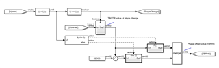
Hi, is it possible to implement a custom algorithm on a faster task, e.g., the task on which the ePWM block is executed?
I have successfully implemented the solution from here, but I noticed the "accuracy" depends on the sample time. I'll try to explain:
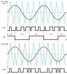
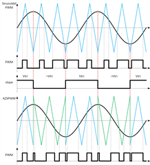
When the slope change is detected, the counter value (ePMW's TBCTR) is recorded and if the slope is rising there is no change to phase offset and TBPHS = TBCTR, and if the slope is falling TBPHS = TBPRD - TBCTR (180 Deg shift).
 CounterShift_R2018a_v000.zip
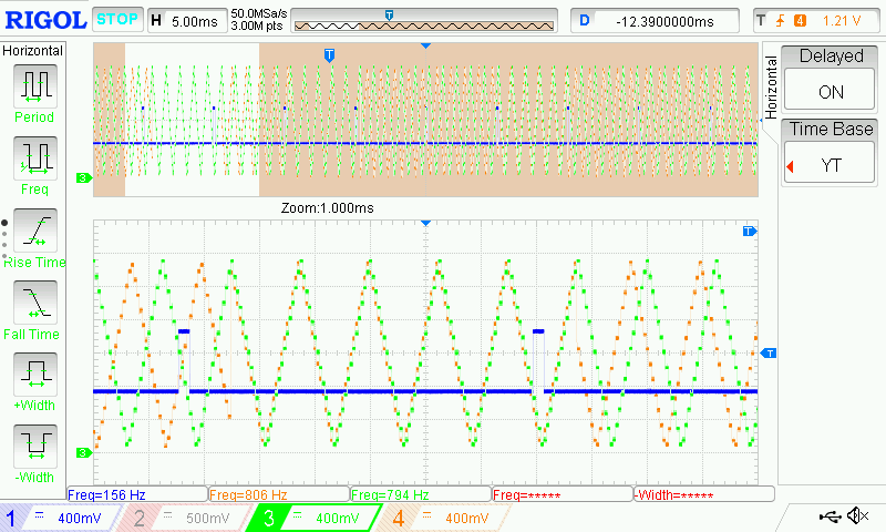
What I noticed is that the accuracy depends on my application sample time. In some cases the counter slope change (Ch4) corresponds to the slope change digital signal (Ch1), and in other cases, it is shifted by several periods. Both figures are recorded during the same run. It ca be seen that there is a delay between the slope change signal and the actual counter slope change and also the slope change does not happen at the 'same' time.
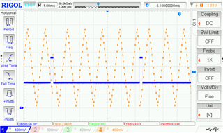
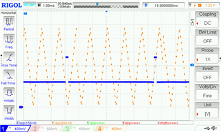
- Ch1: slope change signal
- Ch4: ramp signal (counter value)
In other cases, the sections are not shifted by 180 Deg. Ch3 and Ch4 signals should be in phase where there is no slope change signal, and 180 Deg shifted when there is a slope change. But the figure shows they are not in phase and even between two slope change events are not shifted by the same angle.
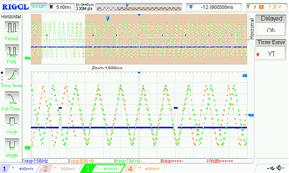
- Ch1: slope change signal
- Ch3: counter signal from another ePMW with the same settings
- Ch4: ramp signal (counter value)
Is this possible to implement this algorithm on some faster ePWM task? Is there any other approach I could try?
This example is done for a switching frequency of 800 Hz. For 50 μs task's sample time, this gives 25 points per switching frequency period (counter). If I go to any higher frequencies, e.g., 8 kHz, the application would read only 2.5 points for each switching frequency period (counter), which is too little for the algorithm at the current sample time to work properly. If I increase my the sample task time, I get overflow

