This thread has been locked.

If you have a related question, please click the "Ask a related question" button in the top right corner. The newly created question will be automatically linked to this question.

TMS320F28379D: ePWM misses pulses at high duty cycles near overmodulation

Part Number: TMS320F28379D
Other Parts Discussed in Thread: C2000WARE

Greetings,

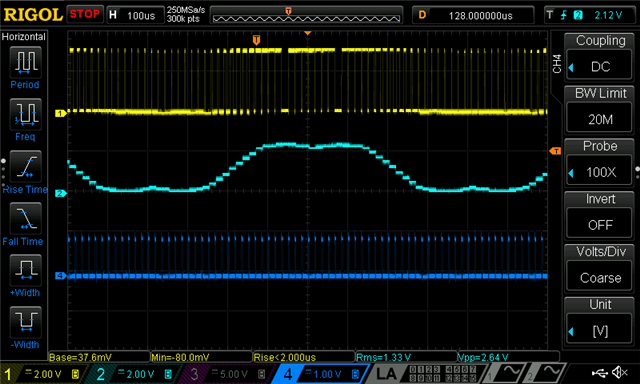
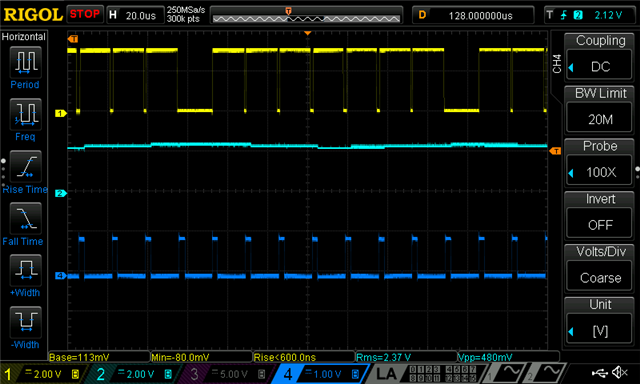
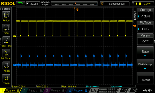
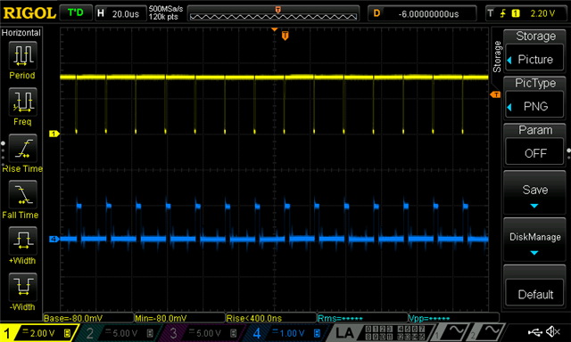
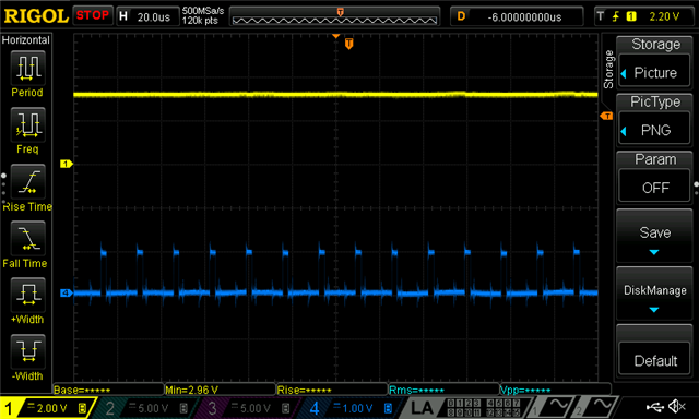
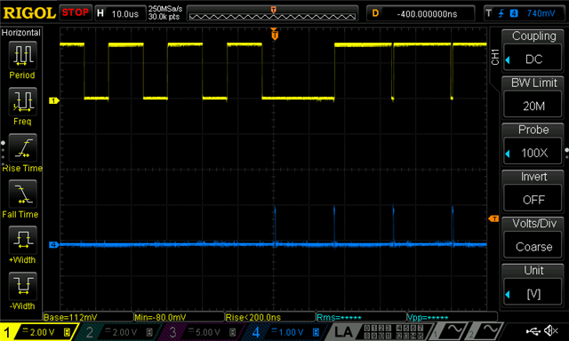
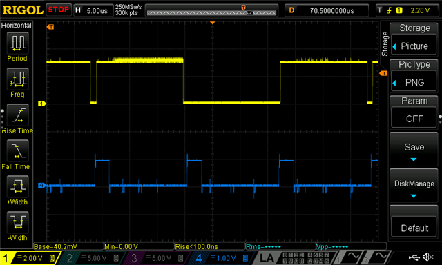
I am having an issue with my EPWM peripheral at high duty cycles (>0.92). The way I have the peripheral configured works well until I approach duty cycles > 0.92. At this point, occasionally a pulse that should be generated is missed. You can see this in the images below. Yellow is the PWM waveform and blue is a timing signal for the ISR, where the CMPA value is updated in the ISR. The blue waveform is set high at the start of the ISR (PWM counter = period, up down count mode), and is set low at the end of the ISR (The ISR takes just under 3 us).

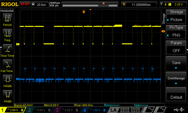
1. Any ideas as to why there are occasional misses?

Here is how I have my peripheral configured: 60 kHz switching frequency, shadow load mode, up down count mode, shadow to active load on counter zero, action qualifier sets pin low during compare match during up count, action qualifier sets pin high during compare match during down count, 200 ns deadband. The ISR occurs at period match.

Here is the configuration code:

EPWM_setPeriodLoadMode(pwmHandle[base], EPWM_PERIOD_SHADOW_LOAD);
        EPWM_setTimeBasePeriod(pwmHandle[base], INV_PWM_TICKS / 2);
        EPWM_setPhaseShift(pwmHandle[base], 0);
        EPWM_setTimeBaseCounter(pwmHandle[base], 0);
        EPWM_setTimeBaseCounterMode(pwmHandle[base], EPWM_COUNTER_MODE_UP_DOWN);
        EPWM_setClockPrescaler(pwmHandle[base], EPWM_CLOCK_DIVIDER_1,
                               EPWM_HSCLOCK_DIVIDER_1);

        EPWM_disablePhaseShiftLoad(pwmHandle[base]);

        // sync "down-stream"
        EPWM_setSyncOutPulseMode(pwmHandle[base],
                                      EPWM_SYNC_OUT_PULSE_ON_COUNTER_ZERO);

        // Counter Compare Submodule Registers
        // set duty 0% initially
        EPWM_setCounterCompareValue(pwmHandle[base], EPWM_COUNTER_COMPARE_A, 0);
        EPWM_setCounterCompareShadowLoadMode(pwmHandle[base],
                                             EPWM_COUNTER_COMPARE_A,
                                             EPWM_COMP_LOAD_ON_CNTR_ZERO);

        // Action Qualifier SubModule Registers
        // Time base counter up equals COMPA and set output pins to low
        // Time base counter down equals COMPA and set output pins to high
        EPWM_setActionQualifierActionComplete(pwmHandle[base], EPWM_AQ_OUTPUT_A,
                (EPWM_ActionQualifierEventAction)(EPWM_AQ_OUTPUT_LOW_UP_CMPA |
                                               EPWM_AQ_OUTPUT_HIGH_DOWN_CMPA));

        // Active high complementary PWMs - Set up the deadband
        EPWM_setRisingEdgeDeadBandDelayInput(pwmHandle[base],
                                             EPWM_DB_INPUT_EPWMA);
        EPWM_setFallingEdgeDeadBandDelayInput(pwmHandle[base],
                                              EPWM_DB_INPUT_EPWMA);

        EPWM_setDeadBandDelayMode(pwmHandle[base], EPWM_DB_RED, true);
        EPWM_setDeadBandDelayMode(pwmHandle[base], EPWM_DB_FED, true);
        EPWM_setDeadBandDelayPolarity(pwmHandle[base], EPWM_DB_RED,
                                      EPWM_DB_POLARITY_ACTIVE_HIGH);
        EPWM_setDeadBandDelayPolarity(pwmHandle[base],
                                      EPWM_DB_FED, EPWM_DB_POLARITY_ACTIVE_LOW);
        // for redcount, fedcount = 200, dead time = 2us -> 10 ns/count
        EPWM_setRisingEdgeDelayCount(pwmHandle[base], DT_DELAY_COUNT);
        EPWM_setFallingEdgeDelayCount(pwmHandle[base], DT_DELAY_COUNT);
  

EPWM_setInterruptSource(EPWM1_BASE, EPWM_INT_TBCTR_PERIOD);

This is for a three phase motor control application. So the ISR performs the field oriented control calculations, and then updates the shadow register with the next duty cycle value. 

2. Shouldn't the shadow register retain it's value and load to the active register each time the PWM counter hits zero? If I perform my ISR at period count, for a 60 kHz PWM (16.67 us period) that means I have 8 us to perform the calcuations and update the shadow register before the counter reaches the zero count, at which point the shadow register value is loaded to the active register.

The result is a large amount of current distortion at high duty cycles when operating the motor. I'm trying to get the motor to operate in overmodulation, but with this bug there is to much current distortion which leads to instability and a loss of control.

Thanks.

  • Hi Ryan,

    Have you tried updating the shadow to active register when PWM counter hits zero or period? 

    To my understanding, yes it should hold what it's value is.

    What I think may be happening is when your counter is counting up, and CTR == Period, your ISR gets triggered to update the CMPA value. However, your CMPA value won't be updated until your counter reaches back to zero which then will update your CMPA register.

    Best regards,

    Ryan Ma

  • Hi Ryan, 

    Thank you for the reply. Yes, I have tried updating the shadow to active register when PWM counter hits zero or period using:

            EPWM_setCounterCompareShadowLoadMode(pwmHandle[base],
                                                 EPWM_COUNTER_COMPARE_A,
                                                 EPWM_COMP_LOAD_ON_CNTR_ZERO_PERIOD);

    However, the same issue persists.

    Another thing I did is use the EPWM_getCounterCompareValue(EPWM1_BASE, EPWM_COUNTER_COMPARE_A) function to verify that the compare register is being loaded with the value I expect. This is the blue waveform generated using the DAC in the images below.

    From this, the value being sent to the compare register is correct (it doesn't send a zero duty cycle command), therefore something else is going on with the ePWM peripheral. The same is happening on the other PWM channels for phases B and C.

  • Hi Ryan,

    Could you also share the code that's within your ISR on how you are setting the CMPA register? We have an example that does update the CMPA registers through ISR found here:

    C:\ti\c2000\C2000Ware_4_03_00_00\driverlib\f2837xd\examples\cpu1\epwm within example 13.

    Could you verify that what you're doing is similar to what is being done in this example?

    Best,

    Ryan Ma

  • Hi Ryan,

    Thanks for the response. Yes, I am updating the CMPA register in a similar manner as the example you pointed to. First the ISR interrupt occurs when the PWM time base counter is equal to period. For 60 kHz, and an EPWM clock divider of 1 in up down count mode, this gives a count of 833. The first thing I do when I jump into the ISR is update the CMPA registers from the previous interrupt's calculations, using the following section of code:

    // ----------------------------------------------------------------------------
    //  Computed Duty and Write to CMPA register
    //  Update Duty Cycle from previous interrupt
    // ----------------------------------------------------------------------------
        EPWM_setCounterCompareValue(EPWM1_BASE, EPWM_COUNTER_COMPARE_A,
                            (uint16_t)((INV_PWM_HALF_TBPRD * svgen.Tc) + INV_PWM_HALF_TBPRD));
        EPWM_setCounterCompareValue(EPWM2_BASE, EPWM_COUNTER_COMPARE_A,
                            (uint16_t)((INV_PWM_HALF_TBPRD * svgen.Ta) + INV_PWM_HALF_TBPRD));
        EPWM_setCounterCompareValue(EPWM3_BASE, EPWM_COUNTER_COMPARE_A,
                            (uint16_t)((INV_PWM_HALF_TBPRD * svgen.Tb) + INV_PWM_HALF_TBPRD));

    Here, INV_PWM_HALF_TBPRD = 416. The svgen.Tx (which is the light blue space vector waveform in the above scope capture) variable varies from -1 to 1, which makes the value being sent into the function vary from 0-832. I spend the rest of the ISR calculating the svgen.Tx duty cycles for the next interrupt. The value doesn't update from the shadow into the active register until the PWM time base counter equals zero.

  • Hi Ryan,

    One thought I am having is possibly doing a software sync (TBCTL[SWFSYNC]) to force a shadow to active load when counter direction is going down. The driverlib for this would be 

    EPWM_forceSyncPulse(uint32_t base);
    Let me know if this helps.
    Best,
    Ryan Ma
  • Hi Ryan, I attempted to software force the synch as you suggested, but this did not resolve the issue. I called the EPWM_forceSynchPulse(EPWM1_BASE) function at the start of the ISR (i.e., this is where the time base counter = period). Do you have any other ideas?

    It is odd that it misses above a particular duty cycle. If I write a constant value to the CMPA register, there is no issue with the PWM missing, as you can see in the plots below:

    Duty Cycle = 90%

    Duty Cycle = 95%

    Duty Cycle = 100%

    This leads me to believe that it only misses the first pulse of the new duty cycle. I will perform some tests to see if I can verify this. I also found this thread, which may be related:

    https://e2e.ti.com/support/microcontrollers/c2000-microcontrollers-group/c2000/f/c2000-microcontrollers-forum/646249/tms320f28075-type-4-epwm-to-generate-full-range-0-100-duty-cycle-waveform-w-o-isr-intervention

    However, this is for overmodulation. I haven't reached overmodulation yet when I experience the issue.

  • Yes it seems like it's missing the first action qualifier event when the CTR is going  in the down direction for some reason and only happening for some events as your waveforms are showing.

    After setting the software sync did you also make sure to change your CMPCTL[LOADASYNC] mux input to be choosing 3? I want to see if this may fix this issue. I am going to reach out to another expert on this to see if this may be some other issue.


  • Allow me to also see if I can replicate this issue here. Just so I can configure what is going wrong and focus on that portion in my project.

    1. You are generating interrupt whenever TBCTR == period

    2. Setting the CMPA values within this ISR and load from shadow to active when TBCTR == 0 

    Only for For duty cycles > 0.9 you're running into this missing event occurring?

    Is your period 120 us? Also CLK div for HSP and CLKDIV is 1?

    Does this sound correct?

  • Hi Ryan,

    1. Yes, interrupt is generated when TBCTR == period

    2. Yes, CMPA values are loaded to shadow at start of ISR and load from shadow to active at TBCTR == 0.

    3. The issue only occurs when the duty cycle > ~0.9, and it seems to only happen on the first pulse.

    4. For up down count mode, I use a Time base period of 833 which gives a PWM frequency of 60 kHz. This gives a pwm period of 16.67 us.

    5. EPWM clock divider is 1. EPWM HS clock divider is also 1.

    6. For the action qualifier, I configure to set pin low during up count compare match and set pin high during down count compare match.

    7. A deadband of 200 ns is set on both the rising and falling edge.

    Thanks!

  • Hi Ryan, I have verified that only a single pulse is missed. In the first scope capture, the duty cycle changes from 0.2 to 0.95. As you can see, the first pulse is missed by the EPWM peripheral at this transition:


    If I change the duty cycle from 0.2 to 0.9, the pulse does not miss, and the EPWM peripheral performs properly:

  • Hi Ryan,

    Sorry I could not get to it yesterday, but I will go ahead and test this out today.

    Best,

    Ryan Ma

  • Hi Ryan,

    Thanks again for your support. I found the bug that is causing my issue. The compare value was not being loaded to the shadow register, it was being loaded to the active register. At the high duty cycle, the comparison needs to be made very fast after the period interrupt. I think that the load to the active register was happening after the comparison, therefore it misses the updated duty cycle. I checked the CMPCTL[SHDWAMODE] bit, and it was indeed set to 1, which is immediate load mode. Manually changing the bit to 0 resolved the problem. Now the shadow loads to the active at TBCTR == 0 and the pulse does not miss. 

    However, this is odd since I was using the following function:

            EPWM_setCounterCompareShadowLoadMode(pwmHandle[base],
                                                 EPWM_COUNTER_COMPARE_A,
                                                 EPWM_COMP_LOAD_ON_CNTR_ZERO);

    I believe this is the function that is supposed to control that bit. There may be a big in the function. Thanks again for your assistance, it is greatly appreciated.

  • Hi Ryan,

    Glad to hear you were able to find out the bug. This is a good thing to note and I will double check on this with the software team.

    Thank you,

    Ryan Ma

  • Hi Ryan,

    The function that controls the shadow A mode would be the one you described. However on reset the default value should have been 0. I am unsure on how that bit was changed to 1 during your run time/debugging.

    I also stepped through an example project and viewed the registers within CCS, the SHDWAMODE bit was set to 0.

    Best,

    Ryan Ma

  • Thanks for checking Ryan. Indeed, you are correct. I just found the cause of the bit getting set to 1. I used the fast current loop example code to start this project, and in the function FLC_initPWM() the shadow load mode is disabled. This was the cause of the bit being set to 1. 

  • Great, I will also note that function down in case this comes up again!

    I will close this thread now 

    Have a great day,

    Ryan Ma