This thread has been locked.

If you have a related question, please click the "Ask a related question" button in the top right corner. The newly created question will be automatically linked to this question.

TMS320F28035: Phase shift between two Sawtooth

Part Number: TMS320F28035

Hi team.

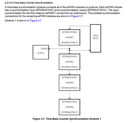
Is there any way that I can introduce phase shift between two sawtooth's (EPwm1Regs.TBCTL.bit.CTRMODE = TB_COUNT_UP;     and      EPwm2Regs.TBCTL.bit.CTRMODE = TB_COUNT_UP;) that are used in PWM.

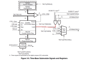
    EPwm1Regs.TBCTL.bit.CTRMODE = TB_COUNT_UP; // Count up
    EPwm1Regs.TBPRD = EPWM1_TIMER_TBPRD;       // Set timer period
    EPwm1Regs.TBCTL.bit.PHSEN = TB_DISABLE;    // Disable phase loading
    EPwm1Regs.TBPHS.half.TBPHS = 0x0000;       // Phase is 0
    EPwm1Regs.TBCTR = 0x0000;                  // Clear counter
    EPwm1Regs.TBCTL.bit.HSPCLKDIV = TB_DIV2;   // Clock ratio to SYSCLKOUT
    EPwm1Regs.TBCTL.bit.CLKDIV = TB_DIV2;
    
    //Other things are removed to keep the code simple
    
    EPwm2Regs.TBCTL.bit.CTRMODE = TB_COUNT_UP; // Count up
    EPwm2Regs.TBPRD = EPWM2_TIMER_TBPRD;       // Set timer period
    EPwm2Regs.TBCTL.bit.PHSEN = TB_DISABLE;    // Disable phase loading
    EPwm2Regs.TBPHS.half.TBPHS = 0x0000;       // Phase is 0
    EPwm2Regs.TBCTR = 0x0000;                  // Clear counter
    EPwm2Regs.TBCTL.bit.HSPCLKDIV = TB_DIV2;   // Clock ratio to SYSCLKOUT
    EPwm2Regs.TBCTL.bit.CLKDIV = TB_DIV2;

  • Hi Puneeth,

    Yes there is a way to enable phase shift between two EPWM modules. 

    I can provide a list of educational material that could help demonstrate Phase shift. Basically what you are going to need to do is enable phase shift load

    EPwm2Regs.TBCTL.bit.PHSEN = TB_ENABLE;

    Then depending on when which SYNCOUT event you want to do a phase shift load you can select it with the TBCTL[SYNCOSEL] = 00. Usually it's typical to have EPWM1 to be master. 

    1. TI training videos found here

    2. App Note for developers configuring PWM provided here

  • Thanks Ryan,

    I've tried everything, still no phase shift but I can see the PWMs perfectly without phase shift even I read the documents that were shared.

    this is the last part left in the whole programming part.

    EPwm1Regs.TBCTL.bit.PRDLD = TB_IMMEDIATE;    // set Immediate load
        EPwm1Regs.TBPRD = period;                  // PWM frequency = 1 / period
        EPwm1Regs.TBCTL.bit.CTRMODE = TB_COUNT_UP;
        EPwm1Regs.TBCTL.bit.PHSEN = TB_ENABLE;         // EPwm1 is the Master
        EPwm1Regs.TBCTL.bit.SYNCOSEL = TB_SYNC_IN;;
        EPwm1Regs.TBCTL.bit.HSPCLKDIV = TB_DIV1;
        EPwm1Regs.TBCTL.bit.CLKDIV = TB_DIV1;
        
        EPwm1Regs.CMPA.half.CMPA = period * (1-d_c_1);       // set duty 50% initially
        EPwm1Regs.CMPA.half.CMPAHR = (1 << 8);       // initialize HRPWM extension
        EPwm1Regs.CMPB = period * (1-d_c_1);                 // set duty 50% initially
        EPwm1Regs.TBPHS.all = 0;
        EPwm1Regs.TBCTR = 0;
    
        EPwm1Regs.CMPCTL.bit.LOADAMODE = CC_CTR_ZERO;
        EPwm1Regs.CMPCTL.bit.LOADBMODE = CC_CTR_ZERO;
        EPwm1Regs.CMPCTL.bit.SHDWAMODE = CC_SHADOW;
        EPwm1Regs.CMPCTL.bit.SHDWBMODE = CC_SHADOW;
    
        EPwm1Regs.AQCTLA.bit.ZRO = AQ_CLEAR;         // PWM toggle low/high
        EPwm1Regs.AQCTLA.bit.CAU = AQ_SET;
        EPwm1Regs.AQCTLB.bit.ZRO = AQ_SET;
        EPwm1Regs.AQCTLB.bit.CBU = AQ_CLEAR;
    
        // Interrupt where we will change the Compare Values
           //
        EPwm1Regs.ETSEL.bit.INTSEL = ET_CTR_ZERO;     // Select INT on Zero event
        EPwm1Regs.ETSEL.bit.INTEN = 1;                // Enable INT
        EPwm1Regs.ETPS.bit.INTPRD = ET_3RD;           // Generate INT on 3rd event
    
        //
        // Start by increasing CMPA & CMPB
        //
        epwm1_info.EPwm_CMPA_Direction = EPWM_CMP_UP;
        epwm1_info.EPwm_CMPB_Direction = EPWM_CMP_UP;
    
    
        EALLOW;
        EPwm1Regs.HRCNFG.all = 0x0;
        EPwm1Regs.HRCNFG.bit.EDGMODE = HR_REP;       // MEP control on falling edge
        EPwm1Regs.HRCNFG.bit.CTLMODE = HR_CMP;
        EPwm1Regs.HRCNFG.bit.HRLOAD  = HR_CTR_ZERO;
        EDIS;
    }
    
    void
    HRPWM2_Config(Uint16 period)
    {
        //
        // ePWM2A toggle low/high with MEP control on Rising edge
        //
        EPwm2Regs.TBCTL.bit.CTRMODE = TB_COUNT_UP;
        EPwm2Regs.TBCTL.bit.PRDLD = TB_IMMEDIATE;   // set Immediate load
        EPwm2Regs.TBPRD = period;                 // PWM frequency = 1 / period
        EPwm2Regs.TBCTL.bit.PHSEN = TB_ENABLE;             // EPwm3 is the Master
        EPwm2Regs.TBPHS.all = period*0.5;  //here TBPHS.half.TBPHS was also tried
        EPwm2Regs.TBCTL.bit.SYNCOSEL = TB_SYNC_IN; // Sync down stream module
        EPwm2Regs.TBCTR = 0x0000; // Clear counter
        EPwm2Regs.TBCTL.bit.HSPCLKDIV = TB_DIV2;
        EPwm2Regs.TBCTL.bit.CLKDIV = TB_DIV2;
    
        EPwm2Regs.CMPA.half.CMPA = period * (1-d_c_2);       // set duty 50% initially
        EPwm2Regs.CMPA.half.CMPAHR = (1 << 8);       // initialize HRPWM extension
        EPwm2Regs.CMPB = period * (1-d_c_2);                 // set duty 50% initially
    
        EPwm2Regs.TBCTL.bit.CTRMODE = TB_COUNT_UP;
        EPwm2Regs.TBCTL.bit.PHSEN = TB_ENABLE;      // EPwm2 is the Master
        EPwm2Regs.TBCTL.bit.SYNCOSEL = TB_SYNC_IN;
        EPwm2Regs.TBCTL.bit.HSPCLKDIV = TB_DIV1;
        EPwm2Regs.TBCTL.bit.CLKDIV = TB_DIV1;
        EPwm2Regs.CMPCTL.bit.LOADAMODE = CC_CTR_ZERO;
        EPwm2Regs.CMPCTL.bit.LOADBMODE = CC_CTR_ZERO;
        EPwm2Regs.CMPCTL.bit.SHDWAMODE = CC_SHADOW;
        EPwm2Regs.CMPCTL.bit.SHDWBMODE = CC_SHADOW;
    
        EPwm2Regs.AQCTLA.bit.ZRO = AQ_CLEAR;         // PWM toggle low/high
        EPwm2Regs.AQCTLA.bit.CAU = AQ_SET;
        EPwm2Regs.AQCTLB.bit.ZRO = AQ_SET;
        EPwm2Regs.AQCTLB.bit.CBU = AQ_CLEAR;
        // Interrupt where we will change the Compare Values
        //
        EPwm2Regs.ETSEL.bit.INTSEL = ET_CTR_ZERO;   // Select INT on Zero event
        EPwm2Regs.ETSEL.bit.INTEN = 1;              // Enable INT
        EPwm2Regs.ETPS.bit.INTPRD = ET_3RD;         // Generate INT on 3rd event
        //
        // Start by increasing CMPA and decreasing CMPB
        //
        epwm2_info.EPwm_CMPA_Direction = EPWM_CMP_UP;
        epwm2_info.EPwm_CMPB_Direction = EPWM_CMP_UP;
        EALLOW;
        EPwm2Regs.HRCNFG.all = 0x0;
        EPwm2Regs.HRCNFG.bit.EDGMODE = HR_REP;       // MEP control on Rising edge
        EPwm2Regs.HRCNFG.bit.CTLMODE = HR_CMP;
        EPwm2Regs.HRCNFG.bit.HRLOAD  = HR_CTR_ZERO;
    
        EDIS;
    }

  • Hi Puneeth,

    EPwm1Regs.TBCTL.bit.PHSEN = TB_ENABLE; // EPwm1 is the Master
    EPwm1Regs.TBCTL.bit.SYNCOSEL = TB_SYNC_IN;;

    Is your epwm1 being synced with an external gpio pin? If so you can validate this on oscilloscope by bringing this to a gpio pin as an output.

    If you're not planning to use a gpio pin in your synchronization, your epwm1 should select a syncout event (TBCTL[SYNCOSEL]).

    If you're planning to use epwm1 as the master and do not have a gpio sending out a syncout, you'll need to disable the PHSEN for epwm1.

  • Hi Ryan,

    This helped to certain extent, but there was something that was not expected

    i. I was expecting phase shift in EPWM2 and EPWM3 but it was observed only in EPWM3.

    ii. Always a fixed 180 degree phase shift was not observed, to obtain which I had modify TBPHS whenever duty cycle varied. 
         For ex: if duty cycle was 20% I had to maintain TBPHS as 420,
                        duty cycle as 50% TBPHS would be 600
                        70% duty cycle TBPHS would be 120
                        at 90% duty TBPHS would be 240

    How to avoid this

    #include "DSP2803x_Device.h"        // DSP2803x Headerfile
    #include "DSP2803x_Examples.h"      // DSP2803x Examples Headerfile
    #include "DSP2803x_EPwm_defines.h"  // useful defines for initialization
    //
    // Function Prototypes
    //
    typedef struct
    {
        volatile struct EPWM_REGS *EPwmRegHandle;
        Uint16 EPwm_CMPA_Direction;
        Uint16 EPwm_CMPB_Direction;
        Uint16 EPwmTimerIntCount;
        Uint16 EPwmMaxCMPA;
        Uint16 EPwmMinCMPA;
        Uint16 EPwmMaxCMPB;
        Uint16 EPwmMinCMPB;
    }EPWM_INFO;
    
    void HRPWM1_Config(Uint16);
    void HRPWM2_Config(Uint16);
    void HRPWM3_Config(Uint16);
    
    #define EPWM_CMP_UP   1
    #define EPWM_CMP_DOWN 0
    
    EPWM_INFO epwm1_info;
    EPWM_INFO epwm2_info;
    EPWM_INFO epwm3_info;
    
    __interrupt void epwm1_isr(void);
    __interrupt void epwm2_isr(void);
    __interrupt void epwm3_isr(void);
    //
    // General System nets - Useful for debug
    //
    
    Uint32 temp;
    float d_c_1 = 0.1;
    float d_c_2 = 0.1;
    float d_c_3 = 0.1;
     //
    // Main
    //
    void main(void)
    {
        InitSysCtrl();
    
        InitEPwm1Gpio();
        InitEPwm2Gpio();
        InitEPwm3Gpio();
        DINT;
    
        InitPieCtrl();
        IER = 0x0000;
        IFR = 0x0000;
    
        InitPieVectTable();
        EALLOW;  // This is needed to write to EALLOW protected registers
        PieVectTable.EPWM1_INT = &epwm1_isr;
        PieVectTable.EPWM2_INT = &epwm2_isr;
        PieVectTable.EPWM3_INT = &epwm3_isr;
        EDIS;    // This is needed to disable write to EALLOW protected registers
    
        EALLOW;
        SysCtrlRegs.PCLKCR0.bit.TBCLKSYNC = 0;
        EDIS;
        HRPWM1_Config(600);      // ePWM1 target, Period = 10
        HRPWM2_Config(600);      // ePWM2 target, Period = 20
        HRPWM3_Config(600);      // ePWM3 target, Period = 10
        EALLOW;
        SysCtrlRegs.PCLKCR0.bit.TBCLKSYNC = 1;
        EDIS;
        IER |= M_INT3;
        PieCtrlRegs.PIEIER3.bit.INTx1 = 1;
        PieCtrlRegs.PIEIER3.bit.INTx2 = 1;
        PieCtrlRegs.PIEIER3.bit.INTx3 = 1;
        EINT;   // Enable Global interrupt INTM
        ERTM;   // Enable Global realtime interrupt DBGM
    
    
    }
    
    // epwm1_isr - EPwm1 ISR
    //
    __interrupt void
    epwm1_isr(void)
    {
        update_compare(&epwm1_info);
        EPwm1Regs.ETCLR.bit.INT = 1;
        PieCtrlRegs.PIEACK.all = PIEACK_GROUP3;
    }
    
    __interrupt void
    epwm2_isr(void)
    {
        update_compare(&epwm2_info);
        EPwm2Regs.ETCLR.bit.INT = 1;
        PieCtrlRegs.PIEACK.all = PIEACK_GROUP3;
    }
    
    __interrupt void
    epwm3_isr(void)
    {
        update_compare(&epwm3_info);
        EPwm3Regs.ETCLR.bit.INT = 1;
        PieCtrlRegs.PIEACK.all = PIEACK_GROUP3;
    }
    
    void
    HRPWM1_Config(Uint16 period)
    {
        //
        // ePWM1A toggle low/high with MEP control on Rising edge
        //
        EPwm1Regs.TBCTL.bit.PRDLD = TB_IMMEDIATE;    // set Immediate load
        EPwm1Regs.TBPRD = period;                  // PWM frequency = 1 / period
    
        EPwm1Regs.CMPA.half.CMPA = period * (1-d_c_1);       // set duty 50% initially
        EPwm1Regs.CMPA.half.CMPAHR = (1 << 8);       // initialize HRPWM extension
        EPwm1Regs.CMPB = period * (1-d_c_1);                 // set duty 50% initially
        EPwm1Regs.TBPHS.all = 0;
        EPwm1Regs.TBCTR = 0;
    
        EPwm1Regs.TBCTL.bit.CTRMODE = TB_COUNT_UP;
        EPwm1Regs.TBCTL.bit.PHSEN = TB_DISABLE;         // EPwm1 is the Master
        EPwm1Regs.TBCTL.bit.SYNCOSEL = TB_SYNC_DISABLE;
        EPwm1Regs.TBCTL.bit.HSPCLKDIV = TB_DIV1;
        EPwm1Regs.TBCTL.bit.CLKDIV = TB_DIV1;
    
        EPwm1Regs.CMPCTL.bit.LOADAMODE = CC_CTR_ZERO;
        EPwm1Regs.CMPCTL.bit.LOADBMODE = CC_CTR_ZERO;
        EPwm1Regs.CMPCTL.bit.SHDWAMODE = CC_SHADOW;
        EPwm1Regs.CMPCTL.bit.SHDWBMODE = CC_SHADOW;
    
        EPwm1Regs.AQCTLA.bit.ZRO = AQ_CLEAR;         // PWM toggle low/high
        EPwm1Regs.AQCTLA.bit.CAU = AQ_SET;
        EPwm1Regs.AQCTLB.bit.ZRO = AQ_SET;
        EPwm1Regs.AQCTLB.bit.CBU = AQ_CLEAR;
    
        // Interrupt where we will change the Compare Values
           //
        EPwm1Regs.ETSEL.bit.INTSEL = ET_CTR_ZERO;     // Select INT on Zero event
        EPwm1Regs.ETSEL.bit.INTEN = 1;                // Enable INT
        EPwm1Regs.ETPS.bit.INTPRD = ET_3RD;           // Generate INT on 3rd event
    
        //
        // Start by increasing CMPA & CMPB
        //
        epwm1_info.EPwm_CMPA_Direction = EPWM_CMP_UP;
        epwm1_info.EPwm_CMPB_Direction = EPWM_CMP_UP;
    
    
        EALLOW;
        EPwm1Regs.HRCNFG.all = 0x0;
        EPwm1Regs.HRCNFG.bit.EDGMODE = HR_REP;       // MEP control on falling edge
        EPwm1Regs.HRCNFG.bit.CTLMODE = HR_CMP;
        EPwm1Regs.HRCNFG.bit.HRLOAD  = HR_CTR_ZERO;
        EDIS;
    }
    
    void
    HRPWM2_Config(Uint16 period)
    {
        //
        // ePWM2A toggle low/high with MEP control on Rising edge
        //
        EPwm2Regs.TBCTL.bit.CTRMODE = TB_COUNT_UP;
        EPwm2Regs.TBCTL.bit.PRDLD = TB_IMMEDIATE;   // set Immediate load
        EPwm2Regs.TBPRD = period;                 // PWM frequency = 1 / period
        EPwm2Regs.TBCTL.bit.PHSEN = TB_ENABLE;             // EPwm3 is the Master
        //EPwm2Regs.TBCTL.bit.PHSDIR = TB_UP;
        EPwm2Regs.TBPHS.all= 00;
        //EPwm2Regs.TBPHS.half.TBPHSHR = 0; // Phase is 0
        EPwm2Regs.TBCTL.bit.SYNCOSEL = TB_CTR_CMPB; // Sync down stream module....TB_CTR_CMPB
        EPwm2Regs.TBCTR = 0x0000; // Clear counter
        EPwm2Regs.TBCTL.bit.HSPCLKDIV = TB_DIV1;
        EPwm2Regs.TBCTL.bit.CLKDIV = TB_DIV1;
    
        EPwm2Regs.CMPA.half.CMPA = period * (d_c_2);       // set duty 50% initially
        EPwm2Regs.CMPA.half.CMPAHR = (1 << 8);       // initialize HRPWM extension
        EPwm2Regs.CMPB = period * (d_c_2);                 // set duty 50% initially
    
           // EPwm2 is the Master
    
        EPwm2Regs.CMPCTL.bit.LOADAMODE = CC_CTR_ZERO;
        EPwm2Regs.CMPCTL.bit.LOADBMODE = CC_CTR_ZERO;
        EPwm2Regs.CMPCTL.bit.SHDWAMODE = CC_SHADOW;
        EPwm2Regs.CMPCTL.bit.SHDWBMODE = CC_SHADOW;
    
        EPwm2Regs.AQCTLA.bit.ZRO = AQ_SET;         // PWM toggle low/high
        EPwm2Regs.AQCTLA.bit.CAU = AQ_CLEAR;
        EPwm2Regs.AQCTLB.bit.ZRO = AQ_CLEAR;
        EPwm2Regs.AQCTLB.bit.CBU = AQ_SET;
        // Interrupt where we will change the Compare Values
        //
        EPwm2Regs.ETSEL.bit.INTSEL = ET_CTR_ZERO;   // Select INT on Zero event
        EPwm2Regs.ETSEL.bit.INTEN = 1;              // Enable INT
        EPwm2Regs.ETPS.bit.INTPRD = ET_3RD;         // Generate INT on 3rd event
        //
        // Start by increasing CMPA and decreasing CMPB
        //
        epwm2_info.EPwm_CMPA_Direction = EPWM_CMP_UP;
        epwm2_info.EPwm_CMPB_Direction = EPWM_CMP_UP;
        EALLOW;
        EPwm2Regs.HRCNFG.all = 0x0;
        EPwm2Regs.HRCNFG.bit.EDGMODE = HR_REP;       // MEP control on Rising edge
        EPwm2Regs.HRCNFG.bit.CTLMODE = HR_CMP;
        EPwm2Regs.HRCNFG.bit.HRLOAD  = HR_CTR_ZERO;
    
        EDIS;
    }
    
    void HRPWM3_Config(Uint16 period)
    {
        //
        // ePWM3 register configuration with HRPWM
        // ePWM3A toggle high/low with MEP control on falling edge
        //
        EPwm3Regs.TBCTL.bit.CTRMODE = TB_COUNT_UP;
        EPwm3Regs.TBCTL.bit.PRDLD = TB_IMMEDIATE;   // set Immediate load
        EPwm3Regs.TBPRD = period;                 // PWM frequency = 1 / period
        EPwm3Regs.TBCTL.bit.PHSEN = TB_ENABLE;             // EPwm3 is the Master
        EPwm3Regs.TBPHS.half.TBPHS= 60;
        EPwm3Regs.TBPHS.half.TBPHSHR = 0; // Phase is 0
        EPwm3Regs.TBCTL.bit.SYNCOSEL = TB_CTR_CMPB; // Sync down stream module
        EPwm3Regs.TBCTR = 0x0000; // Clear counter
        EPwm3Regs.TBCTL.bit.HSPCLKDIV = TB_DIV1;
        EPwm3Regs.TBCTL.bit.CLKDIV = TB_DIV1;
    
        EPwm3Regs.CMPA.half.CMPA = period * (d_c_3);      // set duty 50% initially
        EPwm3Regs.CMPA.half.CMPAHR = (1 << 8);      // initialize HRPWM extension
        EPwm3Regs.CMPB = period * (d_c_3);
    
    
        EPwm3Regs.CMPCTL.bit.LOADAMODE = CC_CTR_ZERO;
        EPwm3Regs.CMPCTL.bit.LOADBMODE = CC_CTR_ZERO;
        EPwm3Regs.CMPCTL.bit.SHDWAMODE = CC_SHADOW;
        EPwm3Regs.CMPCTL.bit.SHDWBMODE = CC_SHADOW;
    
        EPwm3Regs.AQCTLA.bit.ZRO = AQ_SET;           // PWM toggle high/low
        EPwm3Regs.AQCTLA.bit.CAU = AQ_CLEAR;
        EPwm3Regs.AQCTLB.bit.ZRO = AQ_CLEAR;
        EPwm3Regs.AQCTLB.bit.CBU = AQ_SET;
    
        //
        // Interrupt where we will change the Compare Values
        //
        EPwm3Regs.ETSEL.bit.INTSEL = ET_CTR_ZERO;     // Select INT on Zero event
        EPwm3Regs.ETSEL.bit.INTEN = 1;                // Enable INT
        EPwm3Regs.ETPS.bit.INTPRD = ET_3RD;           // Generate INT on 3rd event
    
        //
        // Start by increasing the compare A and decreasing compare B
        //
        epwm3_info.EPwm_CMPA_Direction = EPWM_CMP_UP;
        epwm3_info.EPwm_CMPB_Direction = EPWM_CMP_UP;
    //
    
        EALLOW;
        EPwm3Regs.HRCNFG.all = 0x0;
        EPwm3Regs.HRCNFG.bit.EDGMODE = HR_REP;       // MEP control on falling edge
        EPwm3Regs.HRCNFG.bit.CTLMODE = HR_CMP;
        EPwm3Regs.HRCNFG.bit.HRLOAD  = HR_CTR_ZERO;
        EDIS;
    }
    
    void
    update_compare(EPWM_INFO *epwm_info)
    {
        //
        // Change the CMPA/CMPB values every 10'th interrupt
        //
        if(epwm_info->EPwmTimerIntCount == 10)
        {
            epwm_info->EPwmTimerIntCount = 0;
        }
    
        else
        {
            epwm_info->EPwmTimerIntCount++;
        }
    
        return;
    }
    
    .

  • Hi Puneeth,

    In line 126 of the snippet you sent above, your epwm1 is not sending out a SYNC signal to EPWM2. That is why your EPWM2 is not receiving a phase shift from EPWM1.

    For your second question, you're wanting a fixed 180 degree phase shift correct between all epwm modules?

  • Yes Ryan, I need fixed 180 degree phase shift irrespective of change in duty cycle

  • Okay, and your epwm1 is the master correct?

    Do you want phase shift between epwm1 and epwm 2 to be 180, and epwm1 and epwm3 to be 180?

    From your code it seems that EPWM2 does not have a phase shift value being loaded and only epwm3 does.which is 60. Since your TBPRD is 600, for a 180 degree phase shift, you need to set your TBPHS to be 300. 

    Best,

    Ryan Ma

  • Correct, EPWM1 is master
    I need phase shift 180 with respect to EPWM1 in either in EPWM2 or 3 (any one is sufficient, I'm trying to get phase shift in EPWM3 in that case EPWM2 will have no phase shift, it will be in sync with EPWM1)

    My TBPRD is 600, correct, but when I keep TBPHS as 300 and if duty cycle varies from 10% to 90%, phase shift will not be uniform. 

    Please help if I'm missing something

    --Thanks

    Puneeth

  • Could you show me the waveforms of your duty cycle and what your phase shift values are on an oscilloscope?

    Best,

    Ryan Ma

  • Hi ryan, 

    Please find the screenshot obtained from logic analyser
    In this channel 1 is PWM1A, channel 2 is PWM1B

    Channel 4 PWM3B and Channel 5 is PWM3A

    Frequency of both PWM1 and PWM2 is 100Khz, hence 10 us is the period. 

    The phase shift is mentioned in terms of us (microseconds). TBPHS was maintained 300 constant through out, it can be seen that phase shift is not constant.

    Fig1, PWM1 duty cycle was 10%, PWM3 was 20%

    Fig 2, PWM1 duty cycle was 10%, PWM3 was 30%

    Fig 3, PWM1 duty cycle was 10%, PWM3 was 40%

    Fig 4, PWm1 duty cycle was 10%, PWM3 was 60%

    Also phase shift can be seen in the images.

    --thanks

    Puneeth

  • Hi Puneeth,

    When are you trying to synchronize your epwm's to? Could you try these configurations? I have been able to synchronize and when changing the duty cycle the pwm modules are still syncrhonized to 300 TBPHS.

    I made the synchronization pass through from epwm1 to epwm3. Making sure to enable the synco select for epwm2 to be SYNCIN. I also set the syncout for EPWM1 to be CMPB.

    I have tested this on F2837xD, so there are a few modifications to just change the CMPA/MPB registers, but nothing major.

    Here are my oscilloscope pictures:

    Picture 1: When CMPA = 300 for both EPWM1 and EPWM3 (phase shift = 180)

    Picutre 2: When CMPA = 450 for epwm 3

    //###########################################################################
    //
    // FILE:   epwm_up_aq_cpu01.c
    //
    // TITLE:  Action Qualifier Module - Using up count.
    //
    //! \addtogroup cpu01_example_list
    //! <h1> EPWM Action Qualifier (epwm_up_aq)</h1>
    //!
    //! This example configures ePWM1, ePWM2, ePWM3 to produce an
    //! waveform with independent modulation on EPWMxA and
    //! EPWMxB.
    //!
    //! The compare values CMPA and CMPB are modified within the ePWM's ISR.
    //!
    //! The TB counter is in up count mode for this example.
    //!
    //! View the EPWM1A/B(PA0_GPIO0 & PA1_GPIO1), EPWM2A/B(PA2_GPIO2 & PA3_GPIO3)
    //! and EPWM3A/B(PA4_GPIO4 & PA5_GPIO5) waveforms via an oscilloscope.
    //!
    //
    //###########################################################################
    //
    // $Release Date: $
    // $Copyright:
    // Copyright (C) 2013-2023 Texas Instruments Incorporated - http://www.ti.com/
    //
    // Redistribution and use in source and binary forms, with or without
    // modification, are permitted provided that the following conditions
    // are met:
    //
    //   Redistributions of source code must retain the above copyright
    //   notice, this list of conditions and the following disclaimer.
    //
    //   Redistributions in binary form must reproduce the above copyright
    //   notice, this list of conditions and the following disclaimer in the
    //   documentation and/or other materials provided with the
    //   distribution.
    //
    //   Neither the name of Texas Instruments Incorporated nor the names of
    //   its contributors may be used to endorse or promote products derived
    //   from this software without specific prior written permission.
    //
    // THIS SOFTWARE IS PROVIDED BY THE COPYRIGHT HOLDERS AND CONTRIBUTORS
    // "AS IS" AND ANY EXPRESS OR IMPLIED WARRANTIES, INCLUDING, BUT NOT
    // LIMITED TO, THE IMPLIED WARRANTIES OF MERCHANTABILITY AND FITNESS FOR
    // A PARTICULAR PURPOSE ARE DISCLAIMED. IN NO EVENT SHALL THE COPYRIGHT
    // OWNER OR CONTRIBUTORS BE LIABLE FOR ANY DIRECT, INDIRECT, INCIDENTAL,
    // SPECIAL, EXEMPLARY, OR CONSEQUENTIAL DAMAGES (INCLUDING, BUT NOT
    // LIMITED TO, PROCUREMENT OF SUBSTITUTE GOODS OR SERVICES; LOSS OF USE,
    // DATA, OR PROFITS; OR BUSINESS INTERRUPTION) HOWEVER CAUSED AND ON ANY
    // THEORY OF LIABILITY, WHETHER IN CONTRACT, STRICT LIABILITY, OR TORT
    // (INCLUDING NEGLIGENCE OR OTHERWISE) ARISING IN ANY WAY OUT OF THE USE
    // OF THIS SOFTWARE, EVEN IF ADVISED OF THE POSSIBILITY OF SUCH DAMAGE.
    // $
    //###########################################################################
    
    //
    // Included Files
    //
    #include "F28x_Project.h"
    
    //
    // Defines
    //
    #define EPWM1_TIMER_TBPRD  2000  // Period register
    #define EPWM1_MAX_CMPA     1950
    #define EPWM1_MIN_CMPA       50
    #define EPWM1_MAX_CMPB     1950
    #define EPWM1_MIN_CMPB       50
    
    #define EPWM2_TIMER_TBPRD  2000  // Period register
    #define EPWM2_MAX_CMPA     1950
    #define EPWM2_MIN_CMPA       50
    #define EPWM2_MAX_CMPB     1950
    #define EPWM2_MIN_CMPB       50
    
    #define EPWM3_TIMER_TBPRD  2000  // Period register
    #define EPWM3_MAX_CMPA      950
    #define EPWM3_MIN_CMPA       50
    #define EPWM3_MAX_CMPB     1950
    #define EPWM3_MIN_CMPB     1050
    
    #define EPWM_CMP_UP           1
    #define EPWM_CMP_DOWN         0
    
    //
    // Globals
    //
    typedef struct
    {
        volatile struct EPWM_REGS *EPwmRegHandle;
        Uint16 EPwm_CMPA_Direction;
        Uint16 EPwm_CMPB_Direction;
        Uint16 EPwmTimerIntCount;
        Uint16 EPwmMaxCMPA;
        Uint16 EPwmMinCMPA;
        Uint16 EPwmMaxCMPB;
        Uint16 EPwmMinCMPB;
    }EPWM_INFO;
    
    EPWM_INFO epwm1_info;
    EPWM_INFO epwm2_info;
    EPWM_INFO epwm3_info;
    
    
    #define EPWM_CMP_UP   1
    #define EPWM_CMP_DOWN 0
    
    //
    //  Function Prototypes
    //
    void HRPWM1_Config(Uint16);
    void HRPWM2_Config(Uint16);
    void HRPWM3_Config(Uint16);
    Uint32 temp;
    float d_c_1 = 0.5;
    float d_c_2 = 0.5;
    float d_c_3 = 0.5;
    __interrupt void epwm1_isr(void);
    __interrupt void epwm2_isr(void);
    __interrupt void epwm3_isr(void);
    void update_compare(EPWM_INFO*);
    
    //
    // Main
    //
    void main(void)
    {
    //
    // Step 1. Initialize System Control:
    // PLL, WatchDog, enable Peripheral Clocks
    // This example function is found in the F2837xD_SysCtrl.c file.
    //
        InitSysCtrl();
    
    //
    // Step 2. Initialize GPIO:
    // This example function is found in the F2837xD_Gpio.c file and
    // illustrates how to set the GPIO to it's default state.
    //
    //    InitGpio();
    
    //
    // Enable PWM1, PWM2 and PWM3
    //
        CpuSysRegs.PCLKCR2.bit.EPWM1=1;
        CpuSysRegs.PCLKCR2.bit.EPWM2=1;
        CpuSysRegs.PCLKCR2.bit.EPWM3=1;
    
    //
    // For this case just init GPIO pins for ePWM1, ePWM2, ePWM3
    // These functions are in the F2837xD_EPwm.c file
    //
        InitEPwm1Gpio();
        InitEPwm2Gpio();
        InitEPwm3Gpio();
    
    //
    // Step 3. Clear all interrupts and initialize PIE vector table:
    // Disable CPU interrupts
    //
        DINT;
    
    //
    // Initialize the PIE control registers to their default state.
    // The default state is all PIE interrupts disabled and flags
    // are cleared.
    // This function is found in the F2837xD_PieCtrl.c file.
    //
        InitPieCtrl();
    
    //
    // Disable CPU interrupts and clear all CPU interrupt flags:
    //
        IER = 0x0000;
        IFR = 0x0000;
    
    //
    // Initialize the PIE vector table with pointers to the shell Interrupt
    // Service Routines (ISR).
    // This will populate the entire table, even if the interrupt
    // is not used in this example.  This is useful for debug purposes.
    // The shell ISR routines are found in F2837xD_DefaultIsr.c.
    // This function is found in F2837xD_PieVect.c.
    //
        InitPieVectTable();
    
    //
    // Interrupts that are used in this example are re-mapped to
    // ISR functions found within this file.
    //
        EALLOW; // This is needed to write to EALLOW protected registers
        PieVectTable.EPWM1_INT = &epwm1_isr;
        PieVectTable.EPWM2_INT = &epwm2_isr;
        PieVectTable.EPWM3_INT = &epwm3_isr;
        EDIS;   // This is needed to disable write to EALLOW protected registers
    
    //
    // For this example, only initialize the ePWM
    //
        EALLOW;
        CpuSysRegs.PCLKCR0.bit.TBCLKSYNC = 0;
        EDIS;
    
        HRPWM1_Config(600);      // ePWM1 target, Period = 10
        HRPWM2_Config(600);      // ePWM2 target, Period = 20
        HRPWM3_Config(600);      // ePWM3 target, Period = 10
    
        EALLOW;
        CpuSysRegs.PCLKCR0.bit.TBCLKSYNC = 1;
        EDIS;
    
    //
    // Step 4. User specific code, enable interrupts:
    //
    // Enable CPU INT3 which is connected to EPWM1-3 INT:
    //
        IER |= M_INT3;
    
    //
    // Enable EPWM INTn in the PIE: Group 3 interrupt 1-3
    //
        PieCtrlRegs.PIEIER3.bit.INTx1 = 1;
        PieCtrlRegs.PIEIER3.bit.INTx2 = 1;
        PieCtrlRegs.PIEIER3.bit.INTx3 = 1;
    
    //
    // Enable global Interrupts and higher priority real-time debug events:
    //
        EINT;  // Enable Global interrupt INTM
        ERTM;  // Enable Global realtime interrupt DBGM
    
    //
    // Step 5. IDLE loop. Just sit and loop forever (optional):
    //
        for(;;)
        {
            asm ("  NOP");
        }
    }
    
    //
    // epwm1_isr - EPWM1 ISR to update compare values
    //
    __interrupt void epwm1_isr(void)
    {
        //
        // Update the CMPA and CMPB values
        //
        update_compare(&epwm1_info);
    
        //
        // Clear INT flag for this timer
        //
        EPwm1Regs.ETCLR.bit.INT = 1;
    
        //
        // Acknowledge this interrupt to receive more interrupts from group 3
        //
        PieCtrlRegs.PIEACK.all = PIEACK_GROUP3;
    }
    
    //
    // epwm2_isr - EPWM2 ISR to update compare values
    //
    __interrupt void epwm2_isr(void)
    {
        //
        // Update the CMPA and CMPB values
        //
        update_compare(&epwm2_info);
    
        //
        // Clear INT flag for this timer
        //
        EPwm2Regs.ETCLR.bit.INT = 1;
    
        //
        // Acknowledge this interrupt to receive more interrupts from group 3
        //
        PieCtrlRegs.PIEACK.all = PIEACK_GROUP3;
    }
    
    //
    // epwm3_isr - EPWM3 ISR to update compare values
    //
    __interrupt void epwm3_isr(void)
    {
        //
        // Update the CMPA and CMPB values
        //
        update_compare(&epwm3_info);
    
        //
        // Clear INT flag for this timer
        //
        EPwm3Regs.ETCLR.bit.INT = 1;
    
        //
        // Acknowledge this interrupt to receive more interrupts from group 3
        //
        PieCtrlRegs.PIEACK.all = PIEACK_GROUP3;
    }
    
    //
    // update_compare - Update the compare values for the specified EPWM
    //
    void update_compare(EPWM_INFO *epwm_info)
    {
        //
        // Change the CMPA/CMPB values every 10'th interrupt
        //
        if(epwm_info->EPwmTimerIntCount == 10)
        {
            epwm_info->EPwmTimerIntCount = 0;
        }
    
        else
        {
            epwm_info->EPwmTimerIntCount++;
        }
    
       return;
    }
    void
    HRPWM1_Config(Uint16 period)
    {
        //
        // ePWM1A toggle low/high with MEP control on Rising edge
        //
        EPwm1Regs.TBCTL.bit.PRDLD = TB_IMMEDIATE;    // set Immediate load
        EPwm1Regs.TBPRD = period;                  // PWM frequency = 1 / period
    
        EPwm1Regs.CMPA.bit.CMPA = period * (1-d_c_1);       // set duty 50% initially
        EPwm1Regs.CMPA.bit.CMPAHR = (1 << 8);       // initialize HRPWM extension
        EPwm1Regs.CMPB.bit.CMPB = period * (1-d_c_1);                 // set duty 50% initially
        EPwm1Regs.TBPHS.all = 0;
        EPwm1Regs.TBCTR = 0;
    
        EPwm1Regs.TBCTL.bit.CTRMODE = TB_COUNT_UP;
        EPwm1Regs.TBCTL.bit.PHSEN = TB_DISABLE;         // EPwm1 is the Master
        EPwm1Regs.TBCTL.bit.SYNCOSEL = TB_CTR_CMPB;
        EPwm1Regs.TBCTL.bit.HSPCLKDIV = TB_DIV1;
        EPwm1Regs.TBCTL.bit.CLKDIV = TB_DIV1;
    
        EPwm1Regs.CMPCTL.bit.LOADAMODE = CC_CTR_ZERO;
        EPwm1Regs.CMPCTL.bit.LOADBMODE = CC_CTR_ZERO;
        EPwm1Regs.CMPCTL.bit.SHDWAMODE = CC_SHADOW;
        EPwm1Regs.CMPCTL.bit.SHDWBMODE = CC_SHADOW;
    
        EPwm1Regs.AQCTLA.bit.ZRO = AQ_CLEAR;         // PWM toggle low/high
        EPwm1Regs.AQCTLA.bit.CAU = AQ_SET;
        EPwm1Regs.AQCTLB.bit.ZRO = AQ_SET;
        EPwm1Regs.AQCTLB.bit.CBU = AQ_CLEAR;
    
        // Interrupt where we will change the Compare Values
           //
        EPwm1Regs.ETSEL.bit.INTSEL = ET_CTR_ZERO;     // Select INT on Zero event
        EPwm1Regs.ETSEL.bit.INTEN = 1;                // Enable INT
        EPwm1Regs.ETPS.bit.INTPRD = ET_3RD;           // Generate INT on 3rd event
    
        //
        // Start by increasing CMPA & CMPB
        //
        epwm1_info.EPwm_CMPA_Direction = EPWM_CMP_UP;
        epwm1_info.EPwm_CMPB_Direction = EPWM_CMP_UP;
    
    
        EALLOW;
        EPwm1Regs.HRCNFG.all = 0x0;
        EPwm1Regs.HRCNFG.bit.EDGMODE = HR_REP;       // MEP control on falling edge
        EPwm1Regs.HRCNFG.bit.CTLMODE = HR_CMP;
        EPwm1Regs.HRCNFG.bit.HRLOAD  = HR_CTR_ZERO;
        EDIS;
    }
    
    void
    HRPWM2_Config(Uint16 period)
    {
        //
        // ePWM2A toggle low/high with MEP control on Rising edge
        //
        EPwm2Regs.TBCTL.bit.CTRMODE = TB_COUNT_UP;
        EPwm2Regs.TBCTL.bit.PRDLD = TB_IMMEDIATE;   // set Immediate load
        EPwm2Regs.TBPRD = period;                 // PWM frequency = 1 / period
        EPwm2Regs.TBCTL.bit.PHSEN = TB_ENABLE;             // EPwm3 is the Master
        //EPwm2Regs.TBCTL.bit.PHSDIR = TB_UP;
        EPwm2Regs.TBPHS.all= 00;
        //EPwm2Regs.TBPHS.half.TBPHSHR = 0; // Phase is 0
        EPwm2Regs.TBCTL.bit.SYNCOSEL = TB_SYNC_IN; // Sync down stream module....TB_CTR_CMPB
        EPwm2Regs.TBCTR = 0x0000; // Clear counter
        EPwm2Regs.TBCTL.bit.HSPCLKDIV = TB_DIV1;
        EPwm2Regs.TBCTL.bit.CLKDIV = TB_DIV1;
    
        EPwm2Regs.CMPA.bit.CMPA = period * (d_c_2);       // set duty 50% initially
        EPwm2Regs.CMPA.bit.CMPAHR = (1 << 8);       // initialize HRPWM extension
        EPwm2Regs.CMPB.bit.CMPB = period * (d_c_2);                 // set duty 50% initially
    
           // EPwm2 is the Master
    
        EPwm2Regs.CMPCTL.bit.LOADAMODE = CC_CTR_ZERO;
        EPwm2Regs.CMPCTL.bit.LOADBMODE = CC_CTR_ZERO;
        EPwm2Regs.CMPCTL.bit.SHDWAMODE = CC_SHADOW;
        EPwm2Regs.CMPCTL.bit.SHDWBMODE = CC_SHADOW;
    
        EPwm2Regs.AQCTLA.bit.ZRO = AQ_SET;         // PWM toggle low/high
        EPwm2Regs.AQCTLA.bit.CAU = AQ_CLEAR;
        EPwm2Regs.AQCTLB.bit.ZRO = AQ_CLEAR;
        EPwm2Regs.AQCTLB.bit.CBU = AQ_SET;
        // Interrupt where we will change the Compare Values
        //
        EPwm2Regs.ETSEL.bit.INTSEL = ET_CTR_ZERO;   // Select INT on Zero event
        EPwm2Regs.ETSEL.bit.INTEN = 1;              // Enable INT
        EPwm2Regs.ETPS.bit.INTPRD = ET_3RD;         // Generate INT on 3rd event
        //
        // Start by increasing CMPA and decreasing CMPB
        //
        epwm2_info.EPwm_CMPA_Direction = EPWM_CMP_UP;
        epwm2_info.EPwm_CMPB_Direction = EPWM_CMP_UP;
        EALLOW;
        EPwm2Regs.HRCNFG.all = 0x0;
        EPwm2Regs.HRCNFG.bit.EDGMODE = HR_REP;       // MEP control on Rising edge
        EPwm2Regs.HRCNFG.bit.CTLMODE = HR_CMP;
        EPwm2Regs.HRCNFG.bit.HRLOAD  = HR_CTR_ZERO;
    
        EDIS;
    }
    
    void HRPWM3_Config(Uint16 period)
    {
        //
        // ePWM3 register configuration with HRPWM
        // ePWM3A toggle high/low with MEP control on falling edge
        //
        EPwm3Regs.TBCTL.bit.CTRMODE = TB_COUNT_UP;
        EPwm3Regs.TBCTL.bit.PRDLD = TB_IMMEDIATE;   // set Immediate load
        EPwm3Regs.TBPRD = period;                 // PWM frequency = 1 / period
        EPwm3Regs.TBCTL.bit.PHSEN = TB_ENABLE;             // EPwm3 is the Master
        EPwm3Regs.TBPHS.bit.TBPHS= 300;
        EPwm3Regs.TBPHS.bit.TBPHSHR = 0; // Phase is 0
        EPwm3Regs.TBCTL.bit.SYNCOSEL = TB_SYNC_IN; // Sync down stream module
        EPwm3Regs.TBCTR = 0x0000; // Clear counter
        EPwm3Regs.TBCTL.bit.HSPCLKDIV = TB_DIV1;
        EPwm3Regs.TBCTL.bit.CLKDIV = TB_DIV1;
    
        EPwm3Regs.CMPA.bit.CMPA = period * (d_c_3);      // set duty 50% initially
        EPwm3Regs.CMPA.bit.CMPAHR = (1 << 8);      // initialize HRPWM extension
        EPwm3Regs.CMPB.bit.CMPB = period * (d_c_3);
    
    
        EPwm3Regs.CMPCTL.bit.LOADAMODE = CC_CTR_ZERO;
        EPwm3Regs.CMPCTL.bit.LOADBMODE = CC_CTR_ZERO;
        EPwm3Regs.CMPCTL.bit.SHDWAMODE = CC_SHADOW;
        EPwm3Regs.CMPCTL.bit.SHDWBMODE = CC_SHADOW;
    
        EPwm3Regs.AQCTLA.bit.ZRO = AQ_SET;           // PWM toggle high/low
        EPwm3Regs.AQCTLA.bit.CAU = AQ_CLEAR;
        EPwm3Regs.AQCTLB.bit.ZRO = AQ_CLEAR;
        EPwm3Regs.AQCTLB.bit.CBU = AQ_SET;
    
        //
        // Interrupt where we will change the Compare Values
        //
        EPwm3Regs.ETSEL.bit.INTSEL = ET_CTR_ZERO;     // Select INT on Zero event
        EPwm3Regs.ETSEL.bit.INTEN = 1;                // Enable INT
        EPwm3Regs.ETPS.bit.INTPRD = ET_3RD;           // Generate INT on 3rd event
    
        //
        // Start by increasing the compare A and decreasing compare B
        //
        epwm3_info.EPwm_CMPA_Direction = EPWM_CMP_UP;
        epwm3_info.EPwm_CMPB_Direction = EPWM_CMP_UP;
    //
    
        EALLOW;
        EPwm3Regs.HRCNFG.all = 0x0;
        EPwm3Regs.HRCNFG.bit.EDGMODE = HR_REP;       // MEP control on falling edge
        EPwm3Regs.HRCNFG.bit.CTLMODE = HR_CMP;
        EPwm3Regs.HRCNFG.bit.HRLOAD  = HR_CTR_ZERO;
        EDIS;
    }
    //
    // End of file
    //