This thread has been locked.

If you have a related question, please click the "Ask a related question" button in the top right corner. The newly created question will be automatically linked to this question.

LAUNCHXL-F280039C: CAN communication working, but CAN analyzer not able to detect the bus sigal from Launchpad CANA_RX

Part Number: LAUNCHXL-F280039C

Hi folks,

I have beaglebone and launchpad LAUNCHXL-F280039C connected, and able to do CAN communication. (connection is in the way I mentioned in my other thread https://e2e.ti.com/support/microcontrollers/c2000-microcontrollers-group/c2000/f/c2000-microcontrollers-forum/1201564/launchxl-f280039c-question-about-the-f28003x-launchpad-can-pins-connection-gnd-pin)

And now I am trying out with a logic analyzer (USB Logic Analyzer - 24MHz/8-Channel) to visualize the CAN messages. As instructed, it need connect the GND to the common GND, and a channel connected to CAN RX line to observe the transmitted message.

I first tried to connect the analyzer channel pin to the CAN_RX pin of my beaglebone green. It works that the detected CAN messages content is exactly what transmitted. This proves the CAN communication is working, and the configuration of logic analyzer is correct, too.

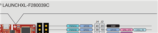
Then I tried to connect the analyzer channel pin to launchpad side. From the LAUNCHXL-F280039C user-guide about its onboard CAN transceiver and routing, my understanding is the GPIO5 pin is CANA_RX for launchpad, and I pushed the routing switch to down state, for sure.

But I couldn't get the CAN transmission detected as I got from the BeagleBone CAN_RX pin. I tried the messaging being BB to launchpad, or launchpad to BB, neither works.

Since the CAN communication is working and the analyzer could detect from BB's CAN_RX, what is the possible issue with my settings, to detect the transmission from the launchpad's CANA_RX?

Thanks in advance for the suggestions.

Regards,

Wei

  • Wei, 

    Apologies for the delayed response. We are looking into it and will get back to you really soon. 

    Thanks.

  • Wei,

              The fact that the Beaglebone and LP are able to communicate over CAN tells me that there are no hardware issues. Exactly where do you measure the CAN receive signal on the LP? You can measure it at pin 5 of S4 (yellow arrow) or pin 4 of U15 (purple arrow). Make sure S4 is in the position shown (red arrow).

  • Hi Hareesh & Sahil,

    Thanks for your reply. 

    I probed for the measurement at J2-Pin19 i.e. the CANA_RX/GPIO5, not on the S4-pin5 / U15-pin4

    Which may be the reason that I didn't get the expected measure.  I will reply later with the result when I get back to the equipments. 

    Regards,

    Wei

  • The CAN signal does not go to J2-pin 19 when the switch is down.

  • Hi Hareesh,

    Thanks for your advice. I tested probing the logic analyzer to S4-pin5 / U15-pin4, they both able to capture the CAN message transmitted, under my current setup.

    So to summarize CAN transmission and the probing to capture CAN message on launchpad F280039C, which having the CAN routing switch / onboard CAN transceiver,  I want to double-check my understandings:

    1. With the CAN routing switch ON(down), it indicates that the onboard CAN transceiver is in effect; the CAN message will be able to be captured on S4-pin5 / U15-pin4. (verified from above efforts). The CAN signal does not go to J2-pin 19 (CANA_RX) in such case.

    2. With the CAN routing switch OFF, the onboard CAN transceiver is not in effect; one could perform CAN transmission with LAUNCHXL-F280039C using the CANA_TX/RX pins (GPIO-4/5), via an external CAN transceiver properly connected; in such case, the CAN message should be able to be captured on J2-pin 19 i.e. CANA_RX pin by logic analyzer.  (I didn't try this setting and verify this theory, but seems reasonable to me).

    Appreciate if you could veirfy or correct my understandings.

    Regards,

    Wei 

  • 1. With the CAN routing switch ON(down), it indicates that the onboard CAN transceiver is in effect; the CAN message will be able to be captured on S4-pin5 / U15-pin4. (verified from above efforts). The CAN signal does not go to J2-pin 19 (CANA_RX) in such case.

    Correct.

    2. With the CAN routing switch OFF, the onboard CAN transceiver is not in effect; one could perform CAN transmission with LAUNCHXL-F280039C using the CANA_TX/RX pins (GPIO-4/5), via an external CAN transceiver properly connected; in such case, the CAN message should be able to be captured on J2-pin 19 i.e. CANA_RX pin by logic analyzer. 

    Correct.