This thread has been locked.
If you have a related question, please click the "Ask a related question" button in the top right corner. The newly created question will be automatically linked to this question.
Hi everyone :
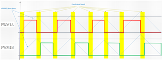
My goal is to keep the dead time of PWM1A and PWM1B constant when the frequency is changed. And the duty cycles of PWM1A and PWM1B are the same.
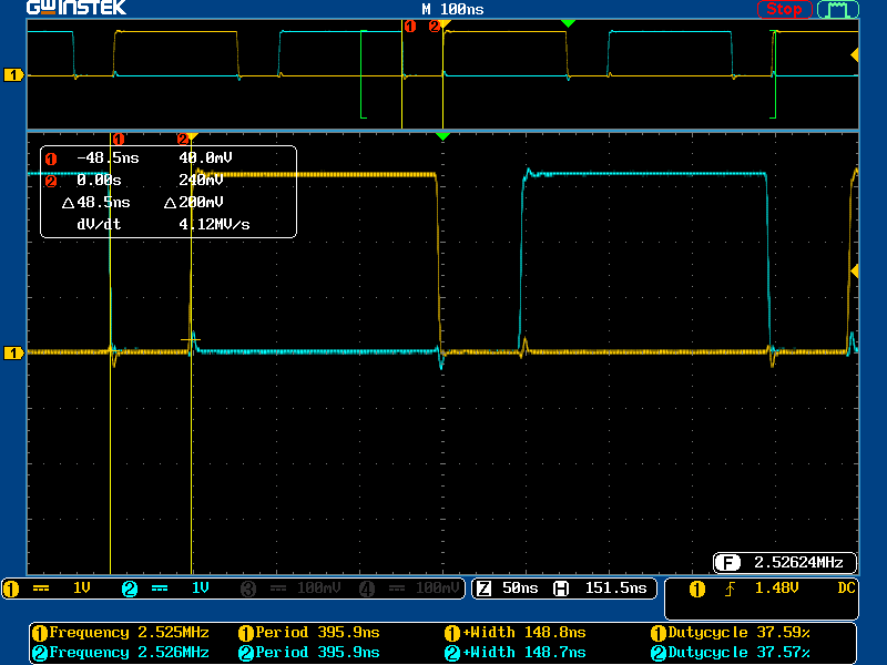
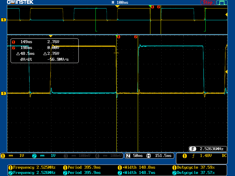
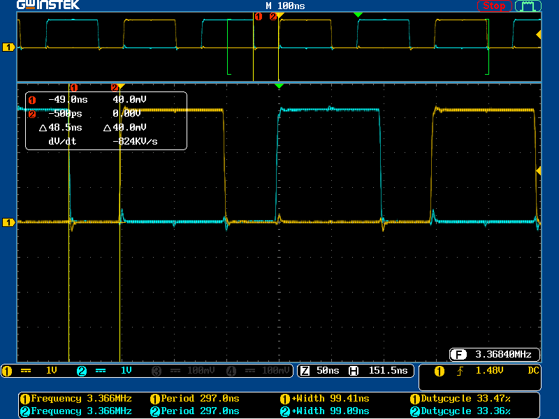
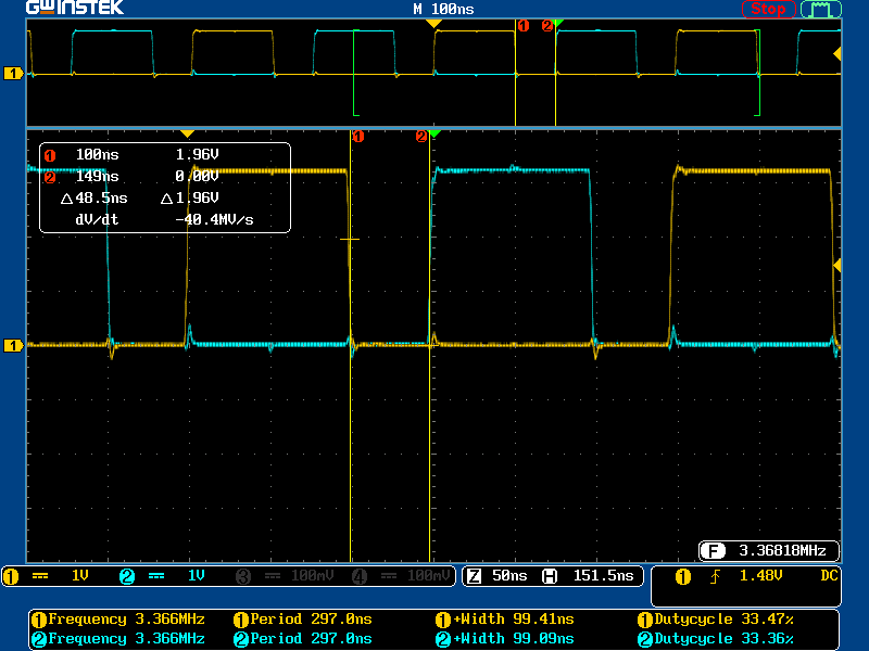
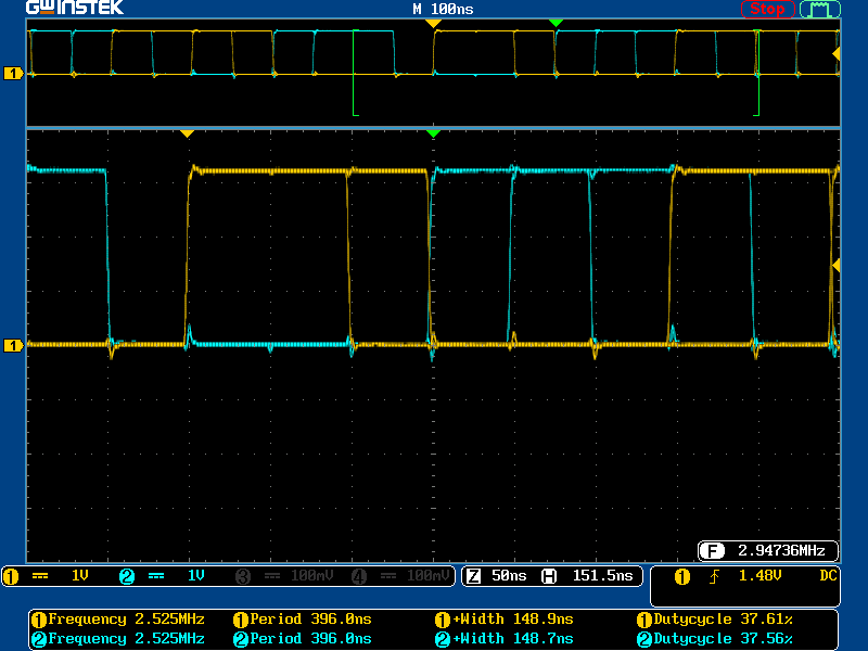
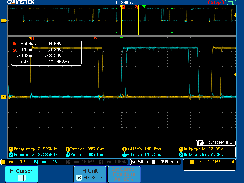
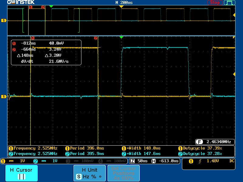
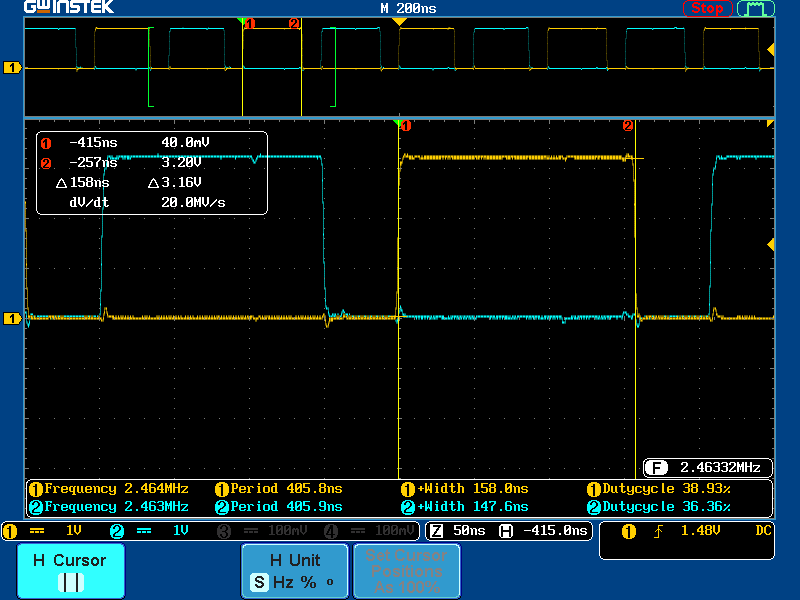
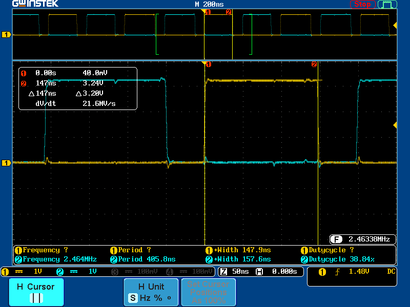
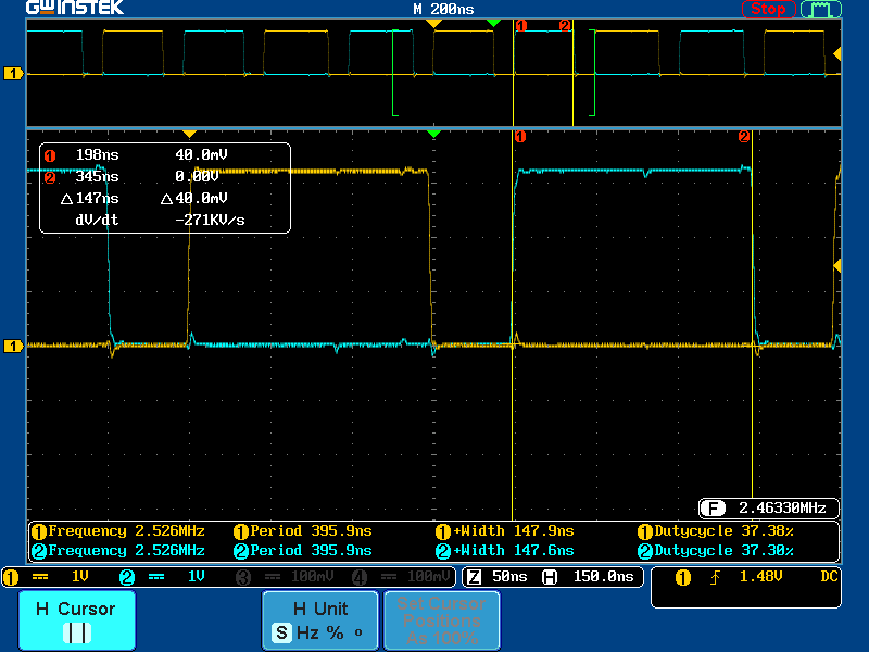
When using ePWM mode, my goal can be achieved, but when I turn on HRPWM, there is a count of jitters.
(The HRPWM MEP Scale Factor Optimization (SFO) library has been used.)
Please give suggestions, thank you!
Hi,
Thanks for contacting e2e forums!
When you enable the HRPWM option, did you make sure that the clock for the HRPWM module is enabled as well? That can cause jitters in the output.
On the fixed dead band for varying frequency, if you load the DBRED and DBFED with correct values, you should be able to achieve this operation.
Hi Aditya Dholakia,
Thanks for your reply, I think I have correctly turned on the HRPWM and his clock, because I use the up and down count bits to align in the middle, the change in TBPRDHR value is accurate and stable on the oscilloscope. But in this mode I can't achieve my goal of constant dead time when the frequency is changed.
As for what I want, when high resolution is turned on, if TBPRDHR is fixed, in addition to the same duty cycle of PWM1A and PWM1B, the dead time of PWM1A and PWM1B must be fixed, and the frequency must be stable. But as I asked, he would have a TBCLK count jitter making the frequency unstable.
Looking forward to your reply~
Can you share the HRPWM initialization code? I can take a look and check if there's something missing and try to replicate the issue on my end.
Hi Aditya Dholakia,
Below is my initialization code
initPWM.h
#ifndef PERIPHERALS_INITPWM_H_ #define PERIPHERALS_INITPWM_H_ #include "common.h" #include "SFO_V8.h" extern void initPWM(void); #define EPWM_softstart 1U #define EPWM_softstart_end 0U #define LAST_EPWM_INDEX_FOR_EXAMPLE 3 #endif /* PERIPHERALS_INITPWM_H_ */
initPWM.c
#include "initPWM.h" #ifdef _FLASH #pragma SET_CODE_SECTION(".TI.ramfunc") #endif //_FLASH // // Globals // int MEP_ScaleFactor; // Global variable used by the SFO library // Result can be used for all HRPWM channels // This variable is also copied to HRMSTEP // register by SFO() function. volatile uint16_t status; uint16_t j; volatile uint32_t ePWM[] = {0, DRI_PRI_BASE, DRI_2ND_BASE}; // // Globals to hold the ePWM information used in this example // /*---------------------------------------------------------------------------------*/ void initHRPWM(void) { HRPWM_setMEPEdgeSelect(ePWM[j], HRPWM_CHANNEL_A, HRPWM_MEP_CTRL_RISING_AND_FALLING_EDGE); HRPWM_setMEPControlMode(ePWM[j], HRPWM_CHANNEL_A, HRPWM_MEP_DUTY_PERIOD_CTRL); HRPWM_setCounterCompareShadowLoadEvent(ePWM[j], HRPWM_CHANNEL_A, HRPWM_LOAD_ON_CNTR_ZERO_PERIOD); HRPWM_setMEPEdgeSelect(ePWM[j], HRPWM_CHANNEL_B, HRPWM_MEP_CTRL_RISING_AND_FALLING_EDGE); HRPWM_setMEPControlMode(ePWM[j], HRPWM_CHANNEL_B, HRPWM_MEP_DUTY_PERIOD_CTRL); HRPWM_setCounterCompareShadowLoadEvent(ePWM[j], HRPWM_CHANNEL_B, HRPWM_LOAD_ON_CNTR_ZERO_PERIOD); // HRPWM_setDeadbandMEPEdgeSelect(ePWM[j],HRPWM_DB_MEP_CTRL_RED_FED); // HRPWM_setRisingEdgeDelayLoadMode(ePWM[j],HRPWM_LOAD_ON_CNTR_ZERO); // HRPWM_setFallingEdgeDelayLoadMode(ePWM[j],HRPWM_LOAD_ON_CNTR_ZERO); HRPWM_setHiResCounterCompareValueOnly(ePWM[j],HRPWM_COUNTER_COMPARE_A,1U); HRPWM_setHiResCounterCompareValueOnly(ePWM[j],HRPWM_COUNTER_COMPARE_B,1U); // HRPWM_setHiResRisingEdgeDelayOnly(ePWM[j], 64U); // HRPWM_setHiResFallingEdgeDelayOnly(ePWM[j], 64U); HRPWM_setHiResTimeBasePeriodOnly(ePWM[j], 128U); HRPWM_enableAutoConversion(ePWM[j]); EPWM_enablePhaseShiftLoad(ePWM[j]); HRPWM_enablePhaseShiftLoad(ePWM[j]); HRPWM_enablePeriodControl(ePWM[j]); EPWM_forceSyncPulse(ePWM[j]); } /*---------------------------------------------------------------------------------*/ void init_EPWM() { sCLA.sPWM.u32PwmBase_PRI = DRI_PRI_BASE; sCLA.sPWM.u32PwmBase_2ND = DRI_2ND_BASE; sCLA.sPWM.u16Period = 20; // Calling SFO() updates the HRMSTEP register with calibrated MEP_ScaleFactor. // HRMSTEP must be populated with a scale factor value prior to enabling // high resolution period control. while(status == SFO_INCOMPLETE) { status = SFO(); if(status == SFO_ERROR) { asm(" ESTOP0"); // SFO function returns 2 if an error occurs & # of MEP } // steps/coarse step exceeds maximum of 255. } for (j=1;j<LAST_EPWM_INDEX_FOR_EXAMPLE;j++){ EPWM_setEmulationMode(ePWM[j], EPWM_EMULATION_FREE_RUN); // TB FREEZE Time Base Counter Mode EPWM_setTimeBaseCounterMode(ePWM[j], EPWM_COUNTER_MODE_STOP_FREEZE); // TB Select Active Period module or Shadow module. EPWM_setPeriodLoadMode(ePWM[j], EPWM_PERIOD_SHADOW_LOAD); // TB Set-up Time Base Period Register EPWM_setTimeBasePeriod(ePWM[j], sCLA.sPWM.u16Period); // TB Set-up Time Base Phase Register EPWM_setPhaseShift(ePWM[j], 0U); // TB Set-up Time Base Counter Register EPWM_setTimeBaseCounter(ePWM[j], 0U); // TB disable Time Base Phase Function EPWM_disablePhaseShiftLoad(ePWM[j]); // TB Set ePWM clock pre-scaler EPWM_setClockPrescaler(ePWM[j],EPWM_CLOCK_DIVIDER_1,EPWM_HSCLOCK_DIVIDER_1); // CC Set up Counter Compare shadowing CMPA and CMPB EPWM_setCounterCompareShadowLoadMode(ePWM[j], EPWM_COUNTER_COMPARE_A, EPWM_COMP_LOAD_ON_CNTR_ZERO); EPWM_setCounterCompareShadowLoadMode(ePWM[j], EPWM_COUNTER_COMPARE_B, EPWM_COMP_LOAD_ON_CNTR_ZERO); // CC Set-up compare COMPA and COMPB Register EPWM_setCounterCompareValue(ePWM[j], EPWM_COUNTER_COMPARE_A, 5U); EPWM_setCounterCompareValue(ePWM[j], EPWM_COUNTER_COMPARE_B, 5U); // AQ Set actions DRI_PRI_BASE and DRI_2ND_BASE // Set ePWMxA Action EPWM_setActionQualifierAction(ePWM[j], EPWM_AQ_OUTPUT_A, EPWM_AQ_OUTPUT_HIGH, EPWM_AQ_OUTPUT_ON_TIMEBASE_ZERO); EPWM_setActionQualifierAction(ePWM[j], EPWM_AQ_OUTPUT_A, EPWM_AQ_OUTPUT_LOW, EPWM_AQ_OUTPUT_ON_TIMEBASE_PERIOD); EPWM_selectPeriodLoadEvent(ePWM[j], EPWM_SHADOW_LOAD_MODE_COUNTER_ZERO); EPWM_setSyncOutPulseMode(ePWM[j], EPWM_SYNC_OUT_PULSE_DISABLED); // // Set the Dead Band Clock Source // EPWM_setDeadBandCounterClock(ePWM[j], EPWM_DB_COUNTER_CLOCK_HALF_CYCLE); EPWM_setDeadBandControlShadowLoadMode(ePWM[j], EPWM_DB_LOAD_ON_CNTR_ZERO); EPWM_setRisingEdgeDelayCountShadowLoadMode(ePWM[j], EPWM_RED_LOAD_ON_CNTR_ZERO); EPWM_setFallingEdgeDelayCountShadowLoadMode(ePWM[j], EPWM_FED_LOAD_ON_CNTR_ZERO); // // Use EPWMA as the input for both RED and FED // EPWM_setRisingEdgeDeadBandDelayInput(ePWM[j], EPWM_DB_INPUT_EPWMA); EPWM_setFallingEdgeDeadBandDelayInput(ePWM[j], EPWM_DB_INPUT_EPWMA); // // Set the RED and FED values // EPWM_setFallingEdgeDelayCount(ePWM[j], 10); EPWM_setRisingEdgeDelayCount(ePWM[j], 10); // // Invert only the Falling Edge delayed output (AHC) // EPWM_setDeadBandDelayPolarity(ePWM[j], EPWM_DB_RED, EPWM_DB_POLARITY_ACTIVE_HIGH); EPWM_setDeadBandDelayPolarity(ePWM[j], EPWM_DB_FED, EPWM_DB_POLARITY_ACTIVE_LOW); // // Use the delayed signals instead of the original signals // EPWM_setDeadBandDelayMode(ePWM[j], EPWM_DB_RED, true); EPWM_setDeadBandDelayMode(ePWM[j], EPWM_DB_FED, true); // // DO NOT Switch Output A with Output B // EPWM_setDeadBandOutputSwapMode(ePWM[j], EPWM_DB_OUTPUT_A, false); EPWM_setDeadBandOutputSwapMode(ePWM[j], EPWM_DB_OUTPUT_B, false); // // initHRPWM(); EPWM_setTimeBaseCounterMode(ePWM[j], EPWM_COUNTER_MODE_UP_DOWN); // ======================================================================== } /*----------------------------Start enabling SOCA -----------------------------*/ EPWM_setCounterCompareShadowLoadMode(DRI_2ND_BASE, EPWM_COUNTER_COMPARE_C, EPWM_COMP_LOAD_ON_CNTR_ZERO); EPWM_setCounterCompareValue(DRI_2ND_BASE, EPWM_COUNTER_COMPARE_C, 0U); // // Disable SOCA // EPWM_disableADCTrigger(DRI_2ND_BASE, EPWM_SOC_A); // // Configure the SOC to occur on the first up-count event // EPWM_setADCTriggerSource(DRI_2ND_BASE, EPWM_SOC_A, EPWM_SOC_TBCTR_U_CMPC); EPWM_setADCTriggerEventPrescale(DRI_2ND_BASE, EPWM_SOC_A, 1); } /*---------------------------------------------------------------------------------*/ void initPWM(void) { // Disable sync(Freeze clock to PWM as well) SysCtl_disablePeripheral(SYSCTL_PERIPH_CLK_TBCLKSYNC); // // Configure DRI_PRI_BASE ePWM Mode init_EPWM(); // // Enable the ePWM time base clock before configuring the module SysCtl_enablePeripheral(SYSCTL_PERIPH_CLK_TBCLKSYNC); } #ifdef _FLASH #pragma SET_CODE_SECTION() #endif //_FLASH
Looking forward to your reply~
Hi,
Thanks for sharing. Before I validate on my end, one quick question - Do you see the jitter on all EPWM outputs or on any specific base?
Thanks,
Aditya
Hi Aditya Dholakia,
Here is my waveform when using only ePWM:
When TBPRD is fixed, ePWM is stable.
The ePWM is also stable when I change TBPRD.
When my TBPRD is changing, its DEAD TIME is fixed, and the subsequent ePWM is also stable.
If the above two TBPRD values change continuously, the following situation can be seen from the oscilloscope.
The above actions are also what I hope hrpwm can do.
Here is the waveform when using HRPWM:
TBPRD is fixed, give TBPRDHR a fixed value of 0x8000 (128U).
At this time, I hope that the HRPWM output is accurate and stable, but there is a problem of cycle jitter.
Observing the continuous action with an oscilloscope, I found that the period is changing, but I clearly gave a fixed value.
The above is all my experiments, I hope it will give you a better understanding of my problem.
Looking forward to your reply~
I couldn't find any issue really in the configuration. Would you know if some specific sequence is to be followed or the cause behind the jitter when enabling TBPRDHR with a deadtime usage?
Aditya
Hi,
The following briefly introduces the behavior mode of epwm, and attaches my project file.
I use up and down counting mode for ePWM and set ActionQualifier of ePWM1A to TBPRD = ZRO is high, TBPRD = PERIOD is low, ePWM1B is AHC mode.
as follows:
When TBPRD is fixed, ePWM is stable.
When I change the value of TBPRD, what I want is that the dead time is fixed, output A and output B have the same high time/low time and duty cycle.
This can be achieved in ePWM mode as shown in the scope waveform in the reply above.
But when I enable HRPWM mode, it produces cycle jitter when TBPRD and TBPRDHR are fixed. Refer to the oscilloscope waveform in the reply above.
The measurement method of the oscilloscope is:
Probe magnification uses x10.
Probes use full bandwidth.
Acquire mode selection Peak detection.
Trigger mode selection Normal.
Attached my project
1777.EVM_20230406_DB_FAIL_SHARE.zip
Looking forward to your reply~
Hi Jiang,
Would it be possible for you to run an hrpwm example from C2000Ware and see if you observe any jitter on your end? If you don't, then I would start by comparing the setting within the example and your project.
Also, you could use SysConfig to setup your epwm module (with the hrpwm capability) to see if there are any issues/warnings with your configuration.
1) Download SysConfig: https://www.ti.com/tool/SYSCONFIG
2) After the download, launch SysConfig and under 'Software Product' select your C2000Ware install.
For 'Device' select F28004x and then the pin package you have:
3) Click 'Start'
4) Go to the 'EPWM' module on the left hand side and click the (+) sign
5) Under the 'Global Parameters' at the top of the EPWM module, make sure to select 'Enable Info Mode' and 'Enable Warnings'
5) You can then start configuring the 'hrpwm' module with the settings in your program and address any warnings or info there might be within your own program.
We've captured all TRM notes regarding incorrect setup in this tool.
Best Regards,
Marlyn
Hello,
I've run a hrpwm example from C2000Ware without any thrashing issues.
Although we use the upper and lower counting mode, our duty of period is not a symmetrical comparison in the middle, but the upper counting part controls the duty of the upper leg, and the lower counting part controls the duty of the lower leg. In this case, we turn on HRPWM to control the decimal part of the cycle, which will cause it, the cycle is unstable.
Can you help us to confirm that hrpwm can be used in such mode?
Looking forward to your reply~
Fornyin
Jiang,
Were you able to test out SysConfig?
Can you help us to confirm that hrpwm can be used in such mode?
In general, yes, HRPWM can be used. There are some limitations when using HRPWM which are incorporated into our SysConfig tool and the TRM.
For example, if you are using HRPWM in UPDOWN count mode then you have to use ACTIONS at CMPxU and CMPxD to get the HR EDGES. You also have to stay out of the UNSUPPORTED 3 cycle ranges.
Best Regards,
Marlyn