This thread has been locked.

If you have a related question, please click the "Ask a related question" button in the top right corner. The newly created question will be automatically linked to this question.

TMS320F280041: F280041 phaseshift control configuration

Part Number: TMS320F280041
Other Parts Discussed in Thread: SYSCONFIG

Hi,all

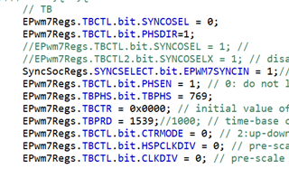
I am try to achieve a 180° phase shift of EPWM7 relative to EPWM6 by adding a phase-shift angle,but just congigure the PHSEN and TBPHS does not serve my purpose.What other registers do I need to configure?

The waveform is as follows,CH5/CH7-EPWM6;CH6/CH8-EPWM7.I want the waveforms of EPWM6 and EPWM7 to complement each other after phase shifting.

  • Hi Ethan,

    In order to synchronize one EPWM module to another, the SYNCOUT signal from the master EPWM must be connected to the SYNCIN signal on the slave EPWM. On F28004x, the connections between SYNCOUT and SYNCIN signals on different EPWM modules are fixed. Refer to the figure "Time-Base Counter Synchronization Scheme" to see the specific connections. 

    For your use-case, the only EPWM modules that can cause a phase shift on EPWM7 are EPWM1 and EPWM4. Is it possible for you to use EPWM4 and EPWM7 rather than EPWM6 and EPWM7? If not, there is a workaround to cause a SYNCIN event on EPWM7 that is sourced from EPWM6 using the CLB and XBARs.

    Thank you,

    Luke

  • Hi,Luke

    thanks for your help.I use EPWM4 as a SYNCOUT source,and EPWM7 receives synchronous pulse signals,180 ° phase shift control can be achieved.

    But during my testing process, the following issues occurred:

    1.When the working frequency is high, the waveform of EPWM7 after phase shifting is lost.

    2.As the operating frequency decreases, the waveform of EPWM7 appears, but EPWM7A is high and EPWM7B is low.

    3.The working frequency continues to decrease, and the waveform of EPWM7 after phase shifting is normal, which is what I want.

    The above issues only occur during the first frequency adjustment after program initialization (frequency from high to low), and the phase shift control is normal during the subsequent adjustment process.The closed-loop control program is as follows:

    The waveform is as follows,CH3/CH4-EPWM4;CH5/CH7-EPWM6;CH6/CH8-EPWM7.

  • To add, I have directly write the PWM configuration under high-frequency conditions as an open-loop program, and the phase shift control is normal without any waveform lost phenomenon.

  • To add, I have directly write the PWM configuration under high-frequency conditions as an open-loop program, and the phase shift control is normal without any waveform lost phenomenon.

  • Hi Ethan,

    Is LLC_FREQadjcontrol called from an ISR? If so what is triggering this ISR? Are you using shadow loading for your epwm periods and CMPA/CMPB values?

    I suspect your action qualifiers are being missed due to TBCTR skipping over your CMPA/CMPB values when the sync event occurs, resulting in no output.

  • How are c1_fed and c1_red being used? I noticed these are being calculated from hard-coded values 80 and 40. Is it possible your falling edge and rising edge delays are too long at high frequencies and overlapping with the subsequent edge?

  • Hi Luke,

    Thanks for your help.My problem has been resolved,the reason for the problem is that the falling edge and rising edge delays are too long at high frequencies.

    Now I have a new problem:My circuit is a bidirectional LLC circuit, During forward operation, EPWM7 can achieve a 180 ° phase shift relative to EPWM4,but during reverse operation,I need to achieve a 180 ° phase shift of EPWM4 relative to EPWM7.By reading the data manual for F28004X,the EPWM7SYNOUT of the EPWM4SYNCIN register bit is reserved,The phase shift configuration function I wrote does not work.

    I would like to know if my understanding is correct, and if so, is there any other way to achieve phase shift control of EPWM4 relative to EPWM7?

    Or may I achieve advanced phase shifting of EPWM4 relative to EPWM7?

  • Hi Ethan,

    There is no direct way to cause EPWM4 to be synced by EPWM7 on F28004x, however there is a workaround to achieve this using the CLB and XBARs as I mentioned previously, I've described it in this thread:

    https://e2e.ti.com/support/microcontrollers/c2000-microcontrollers-group/c2000/f/c2000-microcontrollers-forum/1213188/tms320f280048-q1-epwm-sync-issue-epwm2-master-and-epwm1-slave-configuration

    Let me know if this resolves your issue.

  • Hi Luke,

    I have not used the CLB and XBARs function before.For the method you proposed,My understanding is that:

    1. EPWM7SYNOUT is transmitted to an empty GPIO(ex. GPIO33) port through output X-BAR.

    2. Use the GPIO port as EXTSYNCIN1 and transmit it to the EPWM module through input x-bar

    3. After configuring EPWM4SYNCIN to 101, configure the phase shift angle TBPHS.

    I would like to know if my understanding is correct, and if so, which registers should I configure to implement the Input/Output X-BAR function?

    Also, how to configure EPWM7SYNCOUT as EXTSYNCOUT?

    thanks!

  • Hi Ethan,

    Your understanding is slightly different from my explanation in a previous thread but will actually be a cleaner solution since the the CLB is not necessary :)

    To configure the XBARs I would highly recommend using SysConfig to make this easier. Otherwise, you can use the INPUTxSELECT registers to configure the INPUTXBARs and OUTPUT1MUX0TO15CFG/OUTPUTxENABLE registers to configure the OUTPUTXBARs.

    The SYNCSELECT register is used to select EPWM7SYNCOUT as the EXTSYNCOUT source.

    Let me know if you have any other questions

  • Hi Luke,

    I need to achieve the synchronization effect shown in the figure,but now my program cannot achieve the expected control. My program is as follows. Could you please help me check for any configuration errors.

    My understanding is that the transfer of EPWM7SYNOUT to EXTSYNOUT, EXTSYNOUT to GPIO5, and GPIO5 to EXTSYNCIN1 was not achieved, but I did not find the corresponding register settings in the data manual

    //GPIO5,EXTSYNCOUT
    InputXbarRegs.INPUT3SELECT = 5;
    GpioCtrlRegs.GPADIR.bit.GPIO26 = 0;
    GpioCtrlRegs.GPAPUD.bit.GPIO26 = 0; 
    GpioCtrlRegs.GPAQSEL2.bit.GPIO26 = 3; 

    //EPWM7SYNCOUT

    EPwm7Regs.TBCTL.bit.SYNCOSEL = 1; //Sync Output Select,01: CTR = zero: Time-base counter equal to zero (TBCTR = 0x00)
    SyncSocRegs.SYNCSELECT.bit.SYNCOUT = 2;//10: EPWM7SYNCOUT selected
    OutputXbarRegs.OUTPUT1MUX0TO15CFG.bit.MUX0 = 1; //01 : Select .1 input for Mux0
    OutputXbarRegs.OUTPUT1MUXENABLE.bit.MUX0 = 1; //1: Respective output of Mux0 is enabled to drive the OUTPUT1 of
    GpioCtrlRegs.GPAGMUX2.bit.GPIO5 = 1;
    GpioCtrlRegs.GPAMUX2.bit.GPIO5 = 1;EPwm7Regs.TBCTL.bit.PHSEN = 0; // 0: do not load the TBCTR from the TBPHS
    EPwm7Regs.TBPHS.bit.TBPHS = 0;//phase shift angle

    //EPWM4SYNCIN to EXTSYNCIN1

    EPwm4Regs.TBCTL.bit.SYNCOSEL = 0;
    SyncSocRegs.SYNCSELECT.bit.EPWM4SYNCIN = 5;//101: EXTSYNCIN1 selected
    EPwm4Regs.TBCTL.bit.PHSEN = 1; // 0: do not load the TBCTR from the TBPHS
    EPwm4Regs.TBPHS.bit.TBPHS = 0;

  • Hi Ethan,

    GPIO5 must be configured as an output pin for this to work. Let me know if that resolves your issue.

  • Hi Luke,

    I configured GPIO5 as an outputpin, but it still doesn't work. I think it's because EPWM7SYNCOUT didn't transfer to GPIO5, and GPIO5 didn't transfer to EPWM4SYNCIN.

    I am not familiar with X-BAR and I am not sure which registers should be configured to achieve my goals.so could you please help me check for any configuration errors?

    Here is my code:

    //GPIO5-SYNCO
    GpioCtrlRegs.GPADIR.bit.GPIO5 = 1; 
    GpioCtrlRegs.GPAPUD.bit.GPIO5 = 0; 
    GpioCtrlRegs.GPAQSEL1.bit.GPIO5 = 3; 
    GpioCtrlRegs.GPAMUX1.bit.GPIO5 = 3;//3:OUTPUT XBAR3
    GpioCtrlRegs.GPAGMUX1.bit.GPIO5 = 1;

    EPwm7Regs.TBCTL.bit.SYNCOSEL = 1; //Sync Output Select,01: CTR = zero: Time-base counter equal to zero (TBCTR = 0x00)
    SyncSocRegs.SYNCSELECT.bit.SYNCOUT = 2;//10: EPWM7SYNCOUT selected
    OutputXbarRegs.OUTPUT3MUX0TO15CFG.bit.MUX14=3;//11 : Select .3 input for Mux14
    OutputXbarRegs.OUTPUT3MUXENABLE.bit.MUX14 = 1; //1: Respective output of Mux14 is enabled to drive the OUTPUT3
    OutputXbarRegs.OUTPUTLATCHENABLE.bit.OUTPUT3=1;
    OutputXbarRegs.OUTPUTINV.bit.OUTPUT3=1;
    EPwm7Regs.TBCTL.bit.PHSEN = 0; // 0: do not load the TBCTR from the TBPHS
    EPwm7Regs.TBPHS.bit.TBPHS = 0;//phase shift angle

    InputXbarRegs.INPUT5SELECT = 5;//GPIO5 use X-BAR INPUT5
    SyncSocRegs.SYNCSELECT.bit.EPWM4SYNCIN = 5;//101: EXTSYNCIN1 selected
    EPwm4Regs.TBCTL2.bit.PRDLDSYNC=2;//10: Shadow to Active Load of TBPRD occurs only when a SYNC is received.
    EPwm4Regs.TBCTL.bit.SYNCOSEL = 3;//11:disable EPWMSYNCO
    EPwm4Regs.TBCTL.bit.SWFSYNC = 1;
    EPwm4Regs.TBCTL.bit.PHSEN = 1; // 0: do not load the TBCTR from the TBPHS
    EPwm4Regs.TBPHS.bit.TBPHS = 100;

    THANKS!

  • Hi Ethan,

    Why did you configure OUTPUTINV.bit.OUTPUT3 to be 1. I believe this would result in your EXTSYNCOUT always being high except for when a sync source is generated. Are you able to observe EXTSYNCOUT on GPIO5 via an oscilloscope? Does your EPWM7 output and EPWM4 output look correct? Perhaps the EPWM7 PHSEN was not disabled properly resulting in your TBCTRs being in a constant loop from both EPWMs attemtping to sync eachother simultaneously.

    Other than the OUTPUTINV your code looks correct in terms of properly generating a SYNCOUT signal and sending it to INPUTXBAR5 ->EXTSYNCIN1. I will try to test your code and provide feedback by tomorrow if I discover any other issues.

  • Hi Ethan,

    Apologies for the late response, has this issue been resolved? If not I will try to test your code to uncover any issues.

    Thank you,

    Luke

  • Hi,Luke

    This issue has been resolved.thanks for your help.