


Other Parts Discussed in Thread: CONTROLSUITE
Hi Team,
Here's an issue from the customer may need your help:
After the phase voltage Phs-U, Phs-V, Phs-W and the bus voltage DC-bus are divided and filtered, they are converted into Vfb-u, Vfb-v, Vfb-w and Vfb-bus that can be measured by the ADC.
The PHASEVOLT_MACRO(v) macro calculates Vfb-u, Vfb-v and Vfb-w, right?
What is the function of the LC low-pass filter used here? The amplitude and phase of the phase voltage obtained after filtering should be affected, right? If the phase voltage is not compensated, there is a deviation between the ualpha and ubeta input when using the sliding mode observer (parameters after the phase voltage has been changed by clarke) and the ualpha and ubeta command voltage input by svpwm, right?
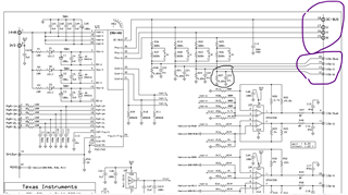
C:\ti\controlSUITE\development_kits\HVMotorCtrl+PfcKit_v2.1\~HVMotorCtrl+PFC-HWdevPkg\HVMotorCtrl+PFCKit-R1.1
--
Thanks & Regards
Yale
