This thread has been locked.

If you have a related question, please click the "Ask a related question" button in the top right corner. The newly created question will be automatically linked to this question.

TMS320F28388D: .

Part Number: TMS320F28388D


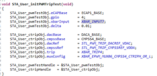
Hi, i'm trying to port the PWM duty cycle self test from 379D to the 388D but the test is run on the CPU2, my problem is that in the self test code there is an instruction to set the  inputselect register (

EALLOW;

HWREGH(base + XBAR_O_INPUT1SELECT + (uint16_t)input) = pin;

EDIS;

) but when i debug it seems that it is not set, in addition to the fact that i can not visualise the register from CPU2 and i have to stop running the CPU1 to be able to see it's content.

  • EALLOW;

    HWREGH(base + XBAR_O_INPUT1SELECT + (uint16_t)input) = pin;

    EDIS;

    I believe this part of the code is executed from CPU1 only, is that correct?

    Also, when you're porting from 379D to 388D there's an additional base parameter which is needed in 388D where you need to explicitly mention the INPUTXBAR_BASE as a valid input. Can you check if you're configuring that correctly?

    It'll be good if you can share that part of the code to understand and debug the issue better.

    Thanks,

    Aditya

  • Hi Abitya, thanks for the quick response;

    Actually the code for the PWM test is executed on CPU2.

    Regarding your second point i didn't quite understand, but i will share the code: 

    The below function is the one that tries to configure the ECAP and in the last instruction where it calls the code i put in the previous message:

    void STL_PWM_Trip_configECAP(const STL_PWM_Trip_TestHandle testHandle)
    {
    uint32_t eCAPBase = testHandle->eCAPBase;
    uint32_t XbarInputBase = INPUTXBAR_BASE;

    //
    // Disable and clear all capture flags and interrupts
    // DID_30_20, DID_30_21
    //
    /*LDRA_INSPECTED 87 S MR:R.18.4 "LDRA Tool Issue, no actual pointer
    arithmetic in code"*/
    /*LDRA_INSPECTED 567 S MR:R.18.1,R.18.4 "LDRA Tool Issue, no actual pointer
    arithmetic in code"*/
    HWREGH(testHandle->eCAPBase + ECAP_O_ECEINT) &= ~0x00FFU;

    /*LDRA_INSPECTED 87 S MR:R.18.4 "LDRA Tool Issue, no actual pointer
    arithmetic in code"*/
    /*LDRA_INSPECTED 567 S MR:R.18.1,R.18.4 "LDRA Tool Issue, no actual pointer
    arithmetic in code"*/
    HWREGH(testHandle->eCAPBase + ECAP_O_ECCLR) = 0x00FFU;

    //
    // Disable CAP1-CAP4 register loads
    // DID_30_22
    //
    ECAP_disableTimeStampCapture(eCAPBase);

    //
    // Stop the counter
    // DID_30_23
    //
    ECAP_stopCounter(eCAPBase);

    //
    // Put the module into capture mode
    // DID_30_24
    //
    ECAP_enableCaptureMode(eCAPBase);

    //
    // Use one-shot mode and stop the capture at event 3
    // DID_30_25
    //
    ECAP_setCaptureMode(eCAPBase, ECAP_ONE_SHOT_CAPTURE_MODE, ECAP_EVENT_3);

    //
    // Set the polarity of events 1-3 to rising, falling, and rising
    // DID_30_26
    //
    ECAP_setEventPolarity(eCAPBase, ECAP_EVENT_1, ECAP_EVNT_RISING_EDGE);
    ECAP_setEventPolarity(eCAPBase, ECAP_EVENT_2, ECAP_EVNT_FALLING_EDGE);
    ECAP_setEventPolarity(eCAPBase, ECAP_EVENT_3, ECAP_EVNT_RISING_EDGE);

    //
    // Reset the counter on event 1 only
    // DID_30_27
    //
    ECAP_enableCounterResetOnEvent(eCAPBase, ECAP_EVENT_1);
    ECAP_disableCounterResetOnEvent(eCAPBase, ECAP_EVENT_2);
    ECAP_disableCounterResetOnEvent(eCAPBase, ECAP_EVENT_3);

    //
    // Enable the module
    // DID_30_28
    //
    ECAP_enableLoadCounter(eCAPBase);
    ECAP_startCounter(eCAPBase);

    //
    // Set up the Input X-BAR
    // DID_30_29
    //
    XBAR_setInputPin(XbarInputBase, testHandle->xbarInput, testHandle->gpio);

    }

    PS: i'm trying to connect Input XBAR_INPUT7 (Gpio 4 where the PWM signal is output ) to ECAP1

    another thing is that i was looking in the forum and i found that in the 388d we should actually use the ECCTL0 register instead of the xbar.inputselect is that correct?

  • You're correct. For the transition from F28379D to F28388D, you'll have to add additional configuration from the ECAP module as well:

    ECAP_selectECAPInput(ECAPx_BASE,ECAP_INPUT_INPUTXBAR7);

    I need to check from the design perspective if this really blocks the writing to INPUTXBAR regs really. Can you try adding the above line of code and see if it works as desired?

    Thanks,

    Aditya

  • Hi, i'm now able to write intp that register (as you can see below) but my self test still doesn't work and i discover that i'm not able to write to the ECAP rearm bit of the ECCTL2 register is that something related to the changes between the 37x and 38x?

  • Hi,

    There was no write protection for ECCTL2 registers in F28379D. The write protection has been added in F28388D.

    If you're using the driverlib function, it'll automatically take care of the change. If you're directly writing to the register using the HWREG approach, you'll have to include EALLOW and EDIS as shown in the image that you've shared.

    Thanks,
    Aditya

  • But what i'm looking for here is why the re-arm bit is not updated even though i write to as a showed you in that code

  • Can you please share the lines of code that you've written for F28379D and F28388D? There's no change other than write protection for F28388D from F28379D.

    BTW, reading the bit will always return 0 since this is only a write-only bit. Are you just checking based on the register view or did you check the functional operation as well? Reading will return 0, you can validate the operation using the functionality.

    Thanks,
    Aditya

  • Aah i guess you are right, but anyway i i checked that i update the memory with the duty cycle but from the ecap side i coumldn't capture anything 

    you can find below the part of the code which test the duty cycle and the called functions

    file: Test.c

    case STA_PWM_DUTY_TEST:
    {
    uint16_t pwmTestStatus;

    STA_User_initPWMTripTest();

    //
    // Have the PWM signal come out on GPIO4
    //
    GPIO_setPinConfig(GPIO_4_EPWM3A);

    //
    // Create a PWM signal and configure the EeCAP
    //
    STL_PWM_Trip_configEPWM(EPWM3_BASE, XBAR_TRIP4,
    STA_USER_PWM_TRIP_PERIOD, 70.0);
    STL_PWM_Trip_configECAP(STA_User_pwmTestHandle);

    //
    // Start looking for the three edges
    //
    STL_PWM_Trip_startECAP(STA_User_pwmTestHandle);

    //
    // Delay long enough to allow the three edges to happen. The
    // delay below is roughly twice the period of the PWM signal.
    //
    STL_Util_delayUS(800U);

    //
    // Check the that the duty cycle is correct
    //
    pwmTestStatus = STL_PWM_Trip_test(STA_User_pwmTestHandle, 70.0);

    if(STA_Tests_injectError)
    {
    //
    // This duty cycle is different from the one expected below
    //
    STL_PWM_Trip_configEPWM(EPWM3_BASE, XBAR_TRIP4,
    STA_USER_PWM_TRIP_PERIOD, 29.8);
    }
    else
    {
    //
    // This duty cycle is the same as the one expected below
    //
    STL_PWM_Trip_configEPWM(EPWM3_BASE, XBAR_TRIP4,
    STA_USER_PWM_TRIP_PERIOD, 32.1);
    }

    //
    // Start looking for the three edges
    //
    STL_PWM_Trip_startECAP(STA_User_pwmTestHandle);

    //
    // Delay long enough to allow the three edges to happen. The
    // delay below is roughly twice the period of the PWM signal.
    //
    STL_Util_delayUS(800U);

    //
    // Check the that the duty cycle is correct
    //
    #if STA_UTIL_PROFILE
    STA_Util_startProfiler(CPUTIMER1_BASE);
    #endif
    pwmTestStatus |= STL_PWM_Trip_test(STA_User_pwmTestHandle, 32.1);
    #if STA_UTIL_PROFILE
    uint32_t cycleCount = STA_Util_stopProfiler(CPUTIMER1_BASE);
    STA_Tests_cycleCounts[STA_PWM_DUTY_TEST] = cycleCount;
    #endif

    if(STL_PWM_TRIP_PASS == pwmTestStatus)
    {
    STA_Tests_passCount++;
    testReport = "\r\n\n\n TEST PASS: PWM Trip Duty Cycle Test!\0";
    }
    else if(STL_PWM_TRIP_FAIL_DUTY_CYCLE == pwmTestStatus)
    {
    testReport = "\r\n\n\n TEST FAIL: PWM Trip Duty Cycle Test!\0";
    }
    else
    {
    //
    // No edges detected. The test failed for the wrong reasons.
    //
    testReport = "\r\n\n\n TEST FAIL: PWM Trip Duty Cycle Test!\0";
    ESTOP0;
    }

    break;
    }

    File: stl_pwm_trip.c  

    //#############################################################################
    //
    // FILE:  stl_pwm_trip.c
    //
    // TITLE: Diagnostic Library PWM software module source
    //
    //#############################################################################
    // $TI Release: F2837xD Diagnostic Library v1.00.02.00 $
    // $Release Date: Mon Dec 18 16:58:06 CST 2017 $
    // $Copyright:
    // Copyright (C) 2016-2017 Texas Instruments Incorporated - http://www.ti.com/
    //
    // Redistribution and use in source and binary forms, with or without 
    // modification, are permitted provided that the following conditions 
    // are met:
    // 
    //   Redistributions of source code must retain the above copyright 
    //   notice, this list of conditions and the following disclaimer.
    // 
    //   Redistributions in binary form must reproduce the above copyright
    //   notice, this list of conditions and the following disclaimer in the 
    //   documentation and/or other materials provided with the   
    //   distribution.
    // 
    //   Neither the name of Texas Instruments Incorporated nor the names of
    //   its contributors may be used to endorse or promote products derived
    //   from this software without specific prior written permission.
    // 
    // THIS SOFTWARE IS PROVIDED BY THE COPYRIGHT HOLDERS AND CONTRIBUTORS 
    // "AS IS" AND ANY EXPRESS OR IMPLIED WARRANTIES, INCLUDING, BUT NOT 
    // LIMITED TO, THE IMPLIED WARRANTIES OF MERCHANTABILITY AND FITNESS FOR
    // A PARTICULAR PURPOSE ARE DISCLAIMED. IN NO EVENT SHALL THE COPYRIGHT 
    // OWNER OR CONTRIBUTORS BE LIABLE FOR ANY DIRECT, INDIRECT, INCIDENTAL, 
    // SPECIAL, EXEMPLARY, OR CONSEQUENTIAL DAMAGES (INCLUDING, BUT NOT 
    // LIMITED TO, PROCUREMENT OF SUBSTITUTE GOODS OR SERVICES; LOSS OF USE,
    // DATA, OR PROFITS; OR BUSINESS INTERRUPTION) HOWEVER CAUSED AND ON ANY
    // THEORY OF LIABILITY, WHETHER IN CONTRACT, STRICT LIABILITY, OR TORT 
    // (INCLUDING NEGLIGENCE OR OTHERWISE) ARISING IN ANY WAY OUT OF THE USE 
    // OF THIS SOFTWARE, EVEN IF ADVISED OF THE POSSIBILITY OF SUCH DAMAGE.
    // $
    //#############################################################################
    
    #include "math.h"
    #include "interrupt.h"
    #include "sysctl.h"
    #include "stl_pwm_trip.h"
    
    //*****************************************************************************
    //
    // STL_PWM_Trip_configEPWM(uint32_t ePWMBase, XBAR_TripNum trip,
    //                         uint16_t period, float32_t dutyCycle)
    //
    //*****************************************************************************
    void STL_PWM_Trip_configEPWM(uint32_t ePWMBase, XBAR_TripNum trip,
                                 uint16_t period, float32_t dutyCycle)
    {
        uint16_t tripInputMask;
        uint16_t dutyCycleCount;
    
        //
        // Freeze the time base counter
        // DID_30_11
        //
        EPWM_setTimeBaseCounterMode(ePWMBase, EPWM_COUNTER_MODE_STOP_FREEZE);
    
        //
        // Set the time base clock prescalers to /1
        // DID_30_12
        //
        EPWM_setClockPrescaler(ePWMBase, EPWM_CLOCK_DIVIDER_1,
                               EPWM_HSCLOCK_DIVIDER_1);
    
        //
        // Set phase shift to 0
        //
        EPWM_setPhaseShift(ePWMBase, 0U);
    
        //
        // Disable the shadow load; the load will be immediate instead
        //
        EPWM_disableCounterCompareShadowLoadMode(ePWMBase,
                                                 EPWM_COUNTER_COMPARE_A);
    
        //
        // Set the compare A value to produce specified duty cycle
        // DID_30_13
        //
        dutyCycleCount = (dutyCycle / (float32_t)100.0) * (float32_t)period;
        EPWM_setCounterCompareValue(ePWMBase, EPWM_COUNTER_COMPARE_A,
                                        dutyCycleCount);
    
        //
        // Set action qualifier behavior on compare A events
        // --> 0 when CTR = CMPA and increasing
        // --> 1 when CTR = CMPA and decreasing
        //
        EPWM_setActionQualifierAction(ePWMBase, EPWM_AQ_OUTPUT_A,
                                      EPWM_AQ_OUTPUT_LOW,
                                      EPWM_AQ_OUTPUT_ON_TIMEBASE_UP_CMPA);
        EPWM_setActionQualifierAction(ePWMBase, EPWM_AQ_OUTPUT_A,
                                      EPWM_AQ_OUTPUT_HIGH,
                                      EPWM_AQ_OUTPUT_ON_TIMEBASE_DOWN_CMPA);
    
        //
        // Configure ePWMxA to output high on TZA TRIP and
        // DID_30_16, DID_30_17
        //
        EPWM_setTripZoneAction(ePWMBase, EPWM_TZ_ACTION_EVENT_TZA,
                               EPWM_TZ_ACTION_HIGH);
        EPWM_setTripZoneAction(ePWMBase, EPWM_TZ_ACTION_EVENT_DCAEVT1,
                               EPWM_TZ_ACTION_HIGH);
    
        //
        // Trigger event when DCAH is high
        //
        EPWM_setTripZoneDigitalCompareEventCondition(ePWMBase,
                                                     EPWM_TZ_DC_OUTPUT_A1,
                                                     EPWM_TZ_EVENT_DCXH_HIGH);
        //
        // Configure DCAH to use the specified as an input
        //
        /*LDRA_INSPECTED 123 S MR:R.10.1,R.10.3,R.10.4 Comment_123S*/
        if((uint16_t)trip < (uint16_t)XBAR_TRIP7)
        {
            tripInputMask = 0x8U << (uint16_t)((uint16_t)trip / 2U);
        }
        else
        {
            tripInputMask = 0x8U << (uint16_t)(((uint16_t)trip / 2U) + 1U);
        }
    
        EPWM_enableDigitalCompareTripCombinationInput(ePWMBase,
                                                      tripInputMask,
                                                      EPWM_DC_TYPE_DCAH);
    
        //
        // Enable DCA as OST
        //
        EPWM_enableTripZoneSignals(ePWMBase, (EPWM_TZ_SIGNAL_OSHT4 |
                                              EPWM_TZ_SIGNAL_DCAEVT1));
    
        //
        // Configure the DCA path to be unfiltered and asynchronous
        //
        EPWM_setDigitalCompareEventSource(ePWMBase,
                                          EPWM_DC_MODULE_A,
                                          EPWM_DC_EVENT_1,
                                          EPWM_DC_EVENT_SOURCE_ORIG_SIGNAL);
    
        //
        // Initializing values for ePWM counter and period
        // DID_30_15
        //
        EPWM_setTimeBaseCounter(ePWMBase, 0U);
        EPWM_setTimeBasePeriod(ePWMBase, period);
    
        //
        // Clear trip flags
        // DID_30_18
        //
        EPWM_clearTripZoneFlag(ePWMBase, EPWM_TZ_INTERRUPT |
                               EPWM_TZ_INTERRUPT_OST);
    
        //
        // Put the time base counter into up-down-count mode
        // DID_30_19
        //
        EPWM_setTimeBaseCounterMode(ePWMBase, EPWM_COUNTER_MODE_UP_DOWN);
    }
    
    //*****************************************************************************
    //
    // STL_PWM_Trip_configECAP(const STL_PWM_Trip_TestHandle testHandle)
    //
    //*****************************************************************************
    void STL_PWM_Trip_configECAP(const STL_PWM_Trip_TestHandle testHandle)
    {
        uint32_t eCAPBase = testHandle->eCAPBase;
        uint32_t XbarInputBase = INPUTXBAR_BASE;
    
        //
        // Disable and clear all capture flags and interrupts
        // DID_30_20, DID_30_21
        //
        /*LDRA_INSPECTED 87 S MR:R.18.4 "LDRA Tool Issue, no actual pointer
          arithmetic in code"*/
        /*LDRA_INSPECTED 567 S MR:R.18.1,R.18.4 "LDRA Tool Issue, no actual pointer
          arithmetic in code"*/
        HWREGH(testHandle->eCAPBase + ECAP_O_ECEINT) &= ~0x00FFU;
    
        /*LDRA_INSPECTED 87 S MR:R.18.4 "LDRA Tool Issue, no actual pointer
          arithmetic in code"*/
        /*LDRA_INSPECTED 567 S MR:R.18.1,R.18.4 "LDRA Tool Issue, no actual pointer
          arithmetic in code"*/
        HWREGH(testHandle->eCAPBase + ECAP_O_ECCLR) = 0x00FFU;
    
        //
        // Disable CAP1-CAP4 register loads
        // DID_30_22
        //
        ECAP_disableTimeStampCapture(eCAPBase);
    
        //
        // Stop the counter
        // DID_30_23
        //
        ECAP_stopCounter(eCAPBase);
    
        //
        // Put the module into capture mode
        // DID_30_24
        //
        ECAP_enableCaptureMode(eCAPBase);
    
        //
        // Use one-shot mode and stop the capture at event 3
        // DID_30_25
        //
        ECAP_setCaptureMode(eCAPBase, ECAP_ONE_SHOT_CAPTURE_MODE, ECAP_EVENT_3);
    
        //
        // Set the polarity of events 1-3 to rising, falling, and rising
        // DID_30_26
        //
        ECAP_setEventPolarity(eCAPBase, ECAP_EVENT_1, ECAP_EVNT_RISING_EDGE);
        ECAP_setEventPolarity(eCAPBase, ECAP_EVENT_2, ECAP_EVNT_FALLING_EDGE);
        ECAP_setEventPolarity(eCAPBase, ECAP_EVENT_3, ECAP_EVNT_RISING_EDGE);
    
        //
        // Reset the counter on event 1 only
        // DID_30_27
        //
        ECAP_enableCounterResetOnEvent(eCAPBase, ECAP_EVENT_1);
        ECAP_disableCounterResetOnEvent(eCAPBase, ECAP_EVENT_2);
        ECAP_disableCounterResetOnEvent(eCAPBase, ECAP_EVENT_3);
    
        //
        // Enable the module
        // DID_30_28
        //
        ECAP_enableLoadCounter(eCAPBase);
        ECAP_startCounter(eCAPBase);
    
        //
        // Set up the Input X-BAR
        // DID_30_29
        //
        XBAR_setInputPin(XbarInputBase, testHandle->xbarInput, testHandle->gpio);
        //added to restor the compatibility with the 37x
        //setting the register ECCCTLx.INPUTSEL
        EALLOW;
    
        HWREGH(ECAP1_BASE + ECCTL0_offset + (uint16_t)input) = pin;
    
        EDIS;
        //ECAP_selectECAPInput(ECAP1_BASE,ECAP_INPUT_INPUTXBAR7);
        //ECAP_selectECAPInput(ECAP1_BASE,ECAP_INPUT_INPUTXBAR7);
    }
    
    //*****************************************************************************
    //
    // STL_PWM_Trip_configCTRIP(const STL_PWM_Trip_CTRIPHandle ctripHandle)
    //
    //*****************************************************************************
    void STL_PWM_Trip_configCTRIP(const STL_PWM_Trip_CTRIPHandle ctripHandle)
    {
        uint32_t cmpssBase = ctripHandle->cmpssBase;
        uint32_t dacBase = ctripHandle->dacBase;
    
        //
        // Set the DAC reference voltage
        // DID_30_30
        //
        DAC_setReferenceVoltage(dacBase, (DAC_ReferenceVoltage)ctripHandle->dacRef);
    
        //
        // Load the DAC value from the shadow on SYSCLK (not PWMSYNC)
        // DID_30_30
        //
        DAC_setLoadMode(dacBase, DAC_LOAD_SYSCLK);
    
        //
        // Enable the DAC output
        // DID_30_31
        //
        DAC_enableOutput(dacBase);
    
        //
        // Set the DAC shadow output to a midpoint value
        // DID_30_32
        //
        DAC_setShadowValue(dacBase, STL_PWM_TRIP_CTRIP_MIDPOINT);
    
        //
        // Enable CMPSS and configure the negative input signal to come from
        // the DAC
        // DID_30_33, DID_30_34, DID_30_35
        //
        CMPSS_enableModule(cmpssBase);
        CMPSS_configHighComparator(cmpssBase, CMPSS_INSRC_DAC);
        CMPSS_configLowComparator(cmpssBase, (CMPSS_INSRC_DAC|CMPSS_INV_INVERTED));
    
        //
        // Set the reference for the DACs and set their values to arbitrary values
        // DID_30_36, DID_30_37
        //
        CMPSS_configDAC(cmpssBase, (uint16_t)(ctripHandle->cmpssRef |
                                        CMPSS_DACVAL_SYSCLK | CMPSS_DACSRC_SHDW));
        CMPSS_setDACValueHigh(cmpssBase, STL_PWM_TRIP_CTRIP_HIGH_THRESH);
        CMPSS_setDACValueLow(cmpssBase, STL_PWM_TRIP_CTRIP_LOW_THRESH);
    
        //
        // Configure the output signals to be asynchronous
        // DID_30_38
        //
        CMPSS_configOutputsHigh(cmpssBase, (CMPSS_TRIP_ASYNC_COMP |
                                            CMPSS_TRIPOUT_ASYNC_COMP));
        CMPSS_configOutputsLow(cmpssBase, (CMPSS_TRIP_ASYNC_COMP |
                                           CMPSS_TRIPOUT_ASYNC_COMP));
    
        //
        // Configure the PWM XBAR
        // DID_30_39
        //
        XBAR_setEPWMMuxConfig(ctripHandle->trip, ctripHandle->muxConfig);
        EALLOW;
    
        /*LDRA_INSPECTED 93 S MR:R.10.1,R.10.3,R.10.4,R.10.5,R.11.1 "LDRA Tool
          Issue, both sides of the operation are the same (uint32_t)"*/
        /*LDRA_INSPECTED 95 S MR:R.11.1,R.11.2,R.11.3,R.11.5,R.11.7 Comment_95S*/
        HWREG(XBAR_EPWM_EN_REG_BASE + (uint16_t)ctripHandle->trip) =
            (uint32_t)1U << (((uint32_t)ctripHandle->muxConfig & 0xFF00U) >> 9);
        EDIS;
    }
    
    //*****************************************************************************
    //
    // STL_PWM_Trip_test(uint32_t eCAPBase, float32_t dutyCycle)
    //
    //*****************************************************************************
    uint16_t STL_PWM_Trip_test(const STL_PWM_Trip_TestHandle testHandle,
                               float32_t dutyCycle)
    {
        uint16_t testStatus;
        uint32_t timeHigh, period;
        float32_t calcDuty;
    
        //
        // Check to make sure all three edges have happened
        // DID_30_48
        //
        if((ECAP_getInterruptSource(testHandle->eCAPBase) &
            ECAP_ISR_SOURCE_CAPTURE_EVENT_3) == ECAP_ISR_SOURCE_CAPTURE_EVENT_3)
        {
            //
            // Calculate the duty cycle based on the values of CAP2 and CAP3
            // DID_30_49
            //
            timeHigh = ECAP_getEventTimeStamp(testHandle->eCAPBase, ECAP_EVENT_2);
            period = ECAP_getEventTimeStamp(testHandle->eCAPBase, ECAP_EVENT_3);
    
            calcDuty = ((float32_t)timeHigh / (float32_t)period) *
                        (float32_t)100.0;
    
            //
            // Check if the calculated duty cycle matches the expected one
            // DID_30_49
            //
            if(fabsf(dutyCycle - calcDuty) <= testHandle->delta)
            {
                //
                // DID_30_51
                //
                testStatus = STL_PWM_TRIP_PASS;
            }
            else
            {
                //
                // Duty cycle didn't match
                // DID_30_50, DID_30_51
                //
                testStatus = STL_PWM_TRIP_FAIL_DUTY_CYCLE;
                STL_Util_setErrorFlag(STL_UTIL_PWM_TRIP_DUTY_CYCLE);
            }
        }
        else
        {
            //
            // eCAP never detected a third edge
            // DID_30_50, DID_30_51
            //
            testStatus = STL_PWM_TRIP_FAIL_MISSING_EDGES;
            STL_Util_setErrorFlag(STL_UTIL_PWM_TRIP_MISSING_EDGES);
        }
    
        //
        // DID_30_51
        //
        return(testStatus);
    }
    
    //
    // End of File
    //
    

  • Also noticed that ECCLR register is not updated when i write 0x8U to it!!

  • ECCLR is again a read-0 write only register. You can know about the read-write properties of any register in the reference manual description.

    Thanks,

    Aditya