Because of the holidays, TI E2E™ design support forum responses will be delayed from Dec. 25 through Jan. 2. Thank you for your patience.

This thread has been locked.

If you have a related question, please click the "Ask a related question" button in the top right corner. The newly created question will be automatically linked to this question.

TMS320F28027F: TMS320F28027F + Drv8305

Part Number: TMS320F28027F
Other Parts Discussed in Thread: DRV8305, , MOTORWARE, TMDSEMU200-U

My application is to rotate BLDC motor from RPM 5000 to 10000. When I am using TI's Launchpad XL Tms320f28027f with DRV8305 motor is rotating as per my requirement. 

But If i  want make my own hardware based on TMS320F28027f, reffering the C2000 Piccalo Launchpad schematic. I have the C2000 Piccalo Launchpad and it has  XDS100 JTAG debugger. Can i use this debugger for Debugging the code on my Custom Board ? If yes, How it can be done ?

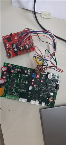
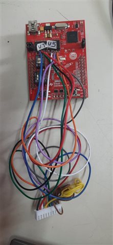
For doing this I have made following changes on Launchpad XL TMS28027F after reading LAUNCHXL F28027F Schematic : 

1. Removed  U1(TMS320F28027F) from board of Launchpad XL .

2. On my custom board where TMS320F28027F is present (which i want to program) following signals i have connected from custom board to Launchpad XL from where U1 IC is removed.

Signals are:

Custom Board (J10 Connector) Launch Pad XL TMSF28027F Purpose
TCK U5 pin no 14 (TCK) JTAG Signals
TDI U5 Pin no 13 (TDI) JTAG Signals
TMS U5 Pin no 12 (TMS) JTAG Signals
TDO U7 pin no 3 (TDO) JTAG Signals
JTAG_TRST U7 pin no 5 (JTAG_TRST) JTAG Signals
SCI_TX U5 Pin no 11 (SCI_RX) Communication with GUI
SCI_RX U7 Pin no 4 (SCI_TX) Communication with GUI

Custom Board Pics.docx       

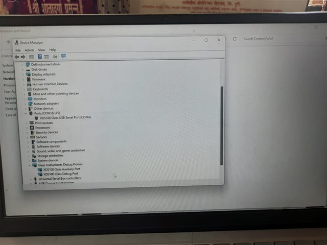
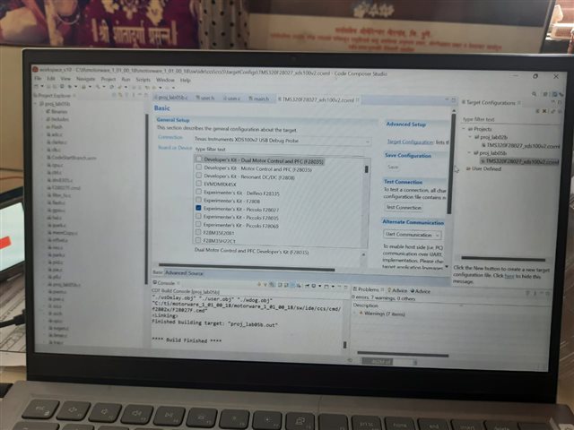
Images are attached for your reference.

I am using Instaspin Universal GUI . Program is getting downloaded successfully and application window also gets displayed. But the values of Bus voltage, Gain Parameters, RS,LS,Flux are not as per given in program and BLDC motor is also not rotating

Thanks 

Vaishali

  • Vaishali,

    Can you please run a "test connection" from CCS and post the result from that test? It seems to me that the JTAG connection is working, but the issue maybe is with the custom board.

  • Hi 

    I didn't get, How to run test connection.

    Do I need to download program in custom board ic from GUI? And then the application window appears . Do you want that application window picture?

    Thanks

    Vaishali

  • It's a feature within CCS. See Figure 5-3 in the document below.

    https://www.ti.com/lit/an/spracf0b/spracf0b.pdf

    Also, just want to confirm, you have a common GND connection between both boards?

  • Yes . Ground is common. I will go through link and will update .

    Thanks

    Vaishali

  • Hello sir

    Attaching herewith JTAG Connection Test results.JTAG connection.docx         

    Problem still persists

    Thanking you in adavnce

    Vaishali

  • After few trials I found following resultJTAG New.docx

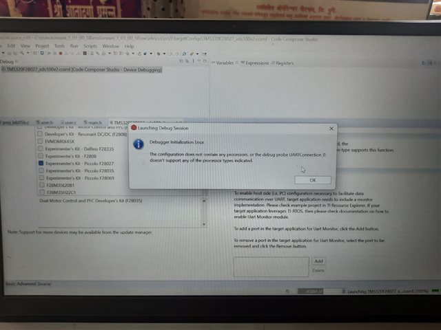
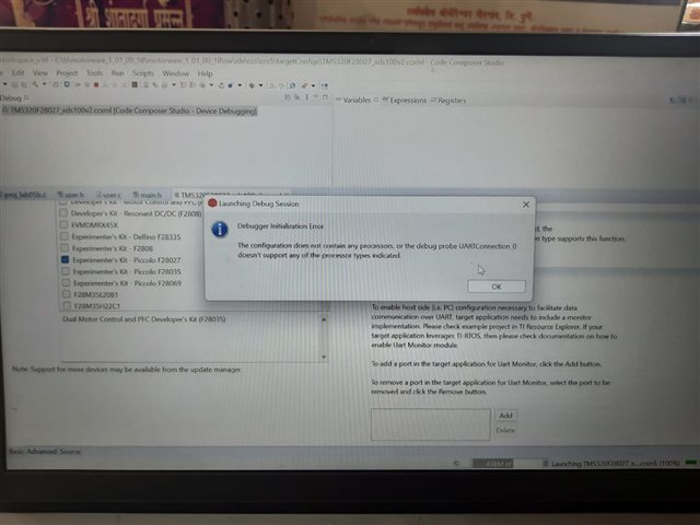
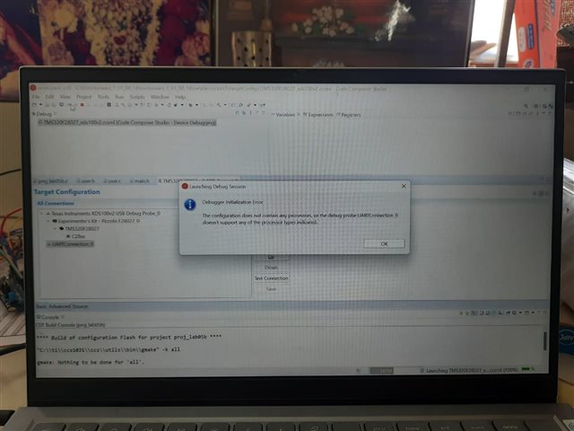
    But Getting debug error as

  • The 1st test result shows that there is signal degradation on the JTAG pins.

    "Some of the values were corrupted - 83.3 percent."

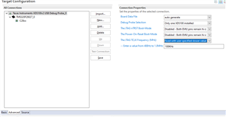
    This is very likely due to the fact that you are wiring two boards together and signal integrity is going to be poor. Try to reduce the JTAG speed in the "Advanced" tab. You will likely need tp play with the speeds until you get a reasonable test result. I'm not sure if that is what you did to get the passing 2nd test result.

    For the debug error, can you show what is in your "advanced" tab?

  • JTAG Updated result test connection.docx       

    Here baud rate selection is automatic.

    I got different result for JTAG connection due to S1 and S4 3pin and 2 pin DIP switches present in Launchxl scematic. For first result where scanning failed 83.3% they were OFF. 

    For next result they were in ON position.

    Sharing sch4810.LAUNCHXL-F28027-SCH.pdfematic also.

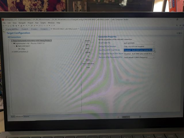
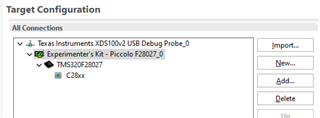
  • What is "UART connection 0"? Did you manually add that? I don't believe that should be there. When I create a new target config, it doesn't show up for me.

  • I have not created it. It automatically comes. 

    I have used SCI_Rx and SCI_Tx. Is it due to that?

    How to remove it?

    Thanks

    Vaishali

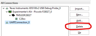
  • I tried again in my end. The only way I see the UART port added is when I click on "Add" under "Alternate Communication". Otherwise this is not there. In any case, you can try to select the "UART" connection and deleting it. 

  • Hi

    At the end of the day these are my results

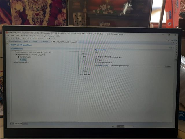
    I could able to download program. But the values of gmotorvars in expression tab are random. Some of them are negative. Values of Gain, RS,LS,Flux are also not as per entered in the program(proj_lab05b.c)

    How to fix this? Sharing screenshots for your reference.

    Regards,

    Vaishali


  • Vaishali,

    I'll ask somebody more familiar with Motorware to review these screenshots & provide more debug steps.

  • You may need to check if the current and voltage sensing signals are good for motor control first since you are using your own board.

    Please follow the steps below to change the example labs and verify the current and voltage signals of the hardware board before run the InsatSPIN labs.


    Please follow the steps to change the example labs and verify the current and voltage signals of the hardware board before run the lab02a/b/c since you are using your own board. Make sure that the current and voltage sampling works well.

    1. Change the PWM and ADC configuration in hal.c refer to the guide, motorware_hal_tutorial.pdf.

    C:\ti\motorware\motorware_1_01_00_18\docs\tutorials


    2. Set correct parameters based on the hardware board in user.h

    #define USER_IQ_FULL_SCALE_VOLTAGE_V           (xx)

    #define USER_VOLTAGE_FILTER_POLE_Hz               (xx)

    #define USER_ADC_FULL_SCALE_VOLTAGE_V       (xx)

    #define USER_IQ_FULL_SCALE_CURRENT_A           (xx)

    #define USER_ADC_FULL_SCALE_CURRENT_A       (xx)


    3. make sure that the sign of the current coefficient in HAL_readAdcData() in hal.h matches the current sensing circuit. Refer to chapter 5.2.2 Current Feedback Polarity in InstaSPIN user's guide (SPRUHJ1, https://www.ti.com/lit/spruhj1) to set the sign of the current scale factor.


    static inline void HAL_readAdcData(HAL_Handle handle,HAL_AdcData_t *pAdcData)

    {

       _iq current_sf = (+/-)HAL_getCurrentScaleFactor(handle);

    }


    4. Follow the instaSPIN lab guide to use lab01b and lab01c to verify your own hardware since you are not using the TI EVM kits and then run the subsequent labs.


    5. Using the lab02b or lab02c and tuning the identification variables parameter below to identify the motor parameters, and use the identified parameters to run the motor if the current and voltage sensing signals are verified and good.

    #define USER_MOTOR_RES_EST_CURRENT      (1.0)                               // A -  10-30% of rated current of the motor

    #define USER_MOTOR_IND_EST_CURRENT      (-1.0)                             // A -  10-30% of rated current of the motor,  just enough to enable rotation

    #define USER_MOTOR_MAX_CURRENT            (5.0)                               // A -  30~150%  of rated current of the motor

    #define USER_MOTOR_FLUX_EST_FREQ_Hz     (40.0)                            // Hz - 10~30% rated frequency of the motor

  • Thank you

    I will try these steps

    As I am using TMS320F28027F , If I purchase TMDSEMU200-U debugger, will it solve my problem?

    Thanks

    Vaishali

  • It doesn't matter the JTAG debugger. You need to change the control parameters (hardware and motor) according to the motor and hardware board you used.