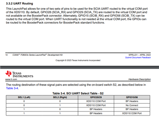
This thread has been locked.

If you have a related question, please click the "Ask a related question" button in the top right corner. The newly created question will be automatically linked to this question.

TMS320F280039C: Cannot Connect To Dev Board

Part Number: LAUNCHXL-F280039C
Other Parts Discussed in Thread: C2000WARE, TMS320F280039C

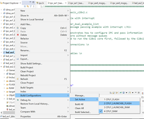
This is my first time working with TI and the C2000 parts so I may be missing things obvious to more seasoned users, but so far this has been quite the painful process. I have a new LAUNCHXL-F280039C that I am trying to flash a simple sample application to. I think I selected the correct debugger (XDS110) in the IDE (not sure why the tools can't detect this) but it's still unable to connect. On the first attempt, the tool told me that the debugger needed to be updated:

The IDE, reset the debugger, downloaded the new firmware and then reset it again into normal mode.

Warning:
A firmware update is required for the XDS110 probe. The current firmware is version 3.0.0.19. The probe must be upgraded to firmware version 3.0.0.25 to be compatible with this software.
Click the "Update" button to update the firmware.
DO NOT UNPLUG THE DEBUG PROBE DURING THE UPDATE.
(Emulation package 9.11.0.00128)

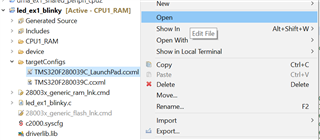
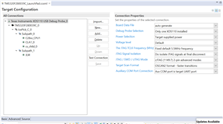
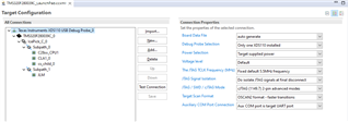
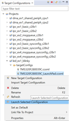
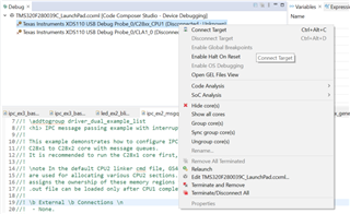
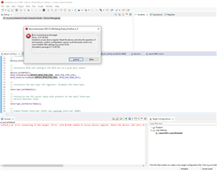
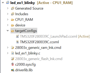
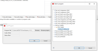
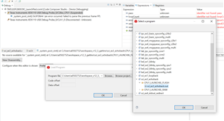
After that the IDE tried to automatically continue with the debug and failed with the below message. The user guide I'm following just says to "Launch the LAUNCHXL-F280039C Target Configuration file and connect to the F28003x device. Ensure that the Target Configuration file is configured to use the 2-pin cJTAG advanced configuration" which isn't much help since I don't see a Target Configuration file. Is there a better guide for debugging with CCS?

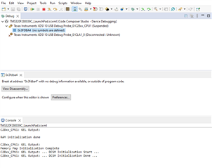
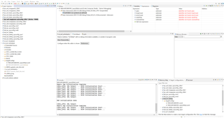
Error connecting to the target:
(Error -2131 @ 0x0)
Unable to access device register. Reset the device, and retry the operation. If error persists, confirm configuration, power-cycle the board, and/or try more reliable JTAG settings (e.g. lower TCLK).
(Emulation package 9.11.0.00128)

This has been preproduced on two brand new boards.

  • Part Number: LAUNCHXL-F280039C

    I'm working with the C2000 for the first time and attempting to compile one of the examples directly from the C2000Ware. I am following the instructions in the user guide and am getting a preprocessor error it seems when I attempt to add the define for the board type (_LAUNCHXL_F280039C)

    option --define is missing its parameter 'NAME[=value]' 

    Any idea what's going on?

  • Hello Dan,

    This may be something out-of-date with the user guide, or it may be referring to creating an example from scratch; if you import an empty project for the F28003x device from C2000Ware should be ready to program as soon as you import it, and to set it up for launchPAD you only need to change the build configuration (right-click on the project folder, select Build Configurations > Set Active > Choose the relevant build configuration for your device). I will check with another expert to see what this note in the user guide refers to.

    Best regards,

    Omer Amir

  • I'm following Section 2.3 from here https://www.ti.com/lit/ug/spruj31/spruj31.pdf?ts=1685102549336

    Without the above change, it does indeed compile, but still fails to connect to the target when I attempt to flash/debug

  • Hello Dan,

    Can you show me the connection error that you get from the console?

    Best regards,

    Omer Amir

  • Since these issues seem related, I will merge the threads and let the other expert address this. This seems more like a debug connection issue.

  • I think the compile issue was separate, and the application is compiling fine if I remove that preprocessor directive. However connecting to the target still fails. 

  • Hi Dan,

    I'm assuming that you have been able to import a CCS example project for F28003x, but please let me know if this is not the case. 

    Could you please open your target configuration file like shown below? I have right-cliciked on the LaunchPad.ccxml file, and selected open. 

    Once this file has opened, could you please click on the 'Advanced' tab at the bottom of the Target Configuration page. Please click on the icon labeled with XDS110 USB Debug Probe so that it is grey like in the below image. Could you please post a screenshot like below of the information shown so that we can confirm it matches the needed settings? 

    From here, could you please click on the 'Test Connection' button? This will help us determine why you are unable to connect to your launchpad.

    Best Regards,

    Ben Collier

  • Hi Ben,

    I have imported sci_ex4_stdout_redirect, and have included the requested info below

  • Hi Dan,

    Thank you, all of your settings look correct for connecting to the launchpad. Could you please select 'Test Connection' and post the output log from that? 

    Best Regards,

    Ben Collier

  • [Start: Texas Instruments XDS110 USB Debug Probe_0]
    
    Execute the command:
    
    %ccs_base%/common/uscif/dbgjtag -f %boarddatafile% -rv -o -S integrity
    
    [Result]
    
    
    -----[Print the board config pathname(s)]------------------------------------
    
    C:\Users\daniel\AppData\Local\TEXASI~1\
        CCS\ccs1230\0\0\BrdDat\testBoard.dat
    
    -----[Print the reset-command software log-file]-----------------------------
    
    This utility has selected a 100/110/510 class product.
    This utility will load the adapter 'jioxds110.dll'.
    The library build date was 'Mar 10 2023'.
    The library build time was '17:27:27'.
    The library package version is '9.11.0.00128'.
    The library component version is '35.35.0.0'.
    The controller does not use a programmable FPGA.
    The controller has a version number of '5' (0x00000005).
    The controller has an insertion length of '0' (0x00000000).
    This utility will attempt to reset the controller.
    This utility has successfully reset the controller.
    
    -----[Print the reset-command hardware log-file]-----------------------------
    
    The scan-path will be reset by toggling the JTAG TRST signal.
    The controller is the XDS110 with USB interface.
    The link from controller to target is direct (without cable).
    The software is configured for XDS110 features.
    The controller cannot monitor the value on the EMU[0] pin.
    The controller cannot monitor the value on the EMU[1] pin.
    The controller cannot control the timing on output pins.
    The controller cannot control the timing on input pins.
    The scan-path link-delay has been set to exactly '0' (0x0000).
    
    -----[Perform the Integrity scan-test on the JTAG IR]------------------------
    
    This test will use blocks of 64 32-bit words.
    This test will be applied just once.
    
    Do a test using 0xFFFFFFFF.
    Scan tests: 1, skipped: 0, failed: 0
    Do a test using 0x00000000.
    Scan tests: 2, skipped: 0, failed: 0
    Do a test using 0xFE03E0E2.
    Scan tests: 3, skipped: 0, failed: 0
    Do a test using 0x01FC1F1D.
    Scan tests: 4, skipped: 0, failed: 0
    Do a test using 0x5533CCAA.
    Scan tests: 5, skipped: 0, failed: 0
    Do a test using 0xAACC3355.
    Scan tests: 6, skipped: 0, failed: 0
    All of the values were scanned correctly.
    
    The JTAG IR Integrity scan-test has succeeded.
    
    -----[Perform the Integrity scan-test on the JTAG DR]------------------------
    
    This test will use blocks of 64 32-bit words.
    This test will be applied just once.
    
    Do a test using 0xFFFFFFFF.
    Scan tests: 1, skipped: 0, failed: 0
    Do a test using 0x00000000.
    Scan tests: 2, skipped: 0, failed: 0
    Do a test using 0xFE03E0E2.
    Scan tests: 3, skipped: 0, failed: 0
    Do a test using 0x01FC1F1D.
    Scan tests: 4, skipped: 0, failed: 0
    Do a test using 0x5533CCAA.
    Scan tests: 5, skipped: 0, failed: 0
    Do a test using 0xAACC3355.
    Scan tests: 6, skipped: 0, failed: 0
    All of the values were scanned correctly.
    
    The JTAG DR Integrity scan-test has succeeded.
    
    [End: Texas Instruments XDS110 USB Debug Probe_0]
    

  • Hi,

    Ok, that test passes as expected. Could you please try putting your device in wait-boot mode by configuring S3 as shown below? 

    Then could you please select View > Target Configurations in CCS? 

    Next could you select Launch Target Configuration as shown below? 

    Then could you please right click on CPU1 in the debug window, and please select 'Connect Target'? 

    Best Regards,

    Ben Collier

  • That seems to work

  • Another update. I tried out the blinky application which I am able to debug and step through, but it doesn't actually blink an LED. The sci_ex3 and sci_ex4 still fail when attempting to connect to the target

  • Hi Dan,

    For the Blinky LED example, could you please right-click on your project and set the build configuration to one of the options for the launchpad? This will change the GPIO being toggled to the correct one for the Launchpad.

    I think that you will have to configure some switches on your Launchpad to get the SCI example to work, but let's make sure that the Blinky example is working for you first. 

    Best Regards,

    Ben Collier 

  • With the build config set to flash the sample works as expected. Thank you for the help with that. Is this documented somewhere? In my past experience the point of the demos is that it's something that works right out of the box. Needing to make changes to the board, or even that the default build config wont produce the expected behavior is not a great out of box experience.

    Please let me know what changes are required for the UART demos or where I can find that info

  • Dan,

    I should have directed you to our training content for new C2000 users earlier. This is C2000 Academy: https://dev.ti.com/tirex/explore/node?node=A__AQKAH9SxFK-9U2eSTHR5-Q__c2000Academy__jEBbtmC__LATEST

    It would have walked you through loading an example to a launchpad, and changing the build configuration to make it work. The changes to the build configuration are necessary since we have other development boards. 

    Did you also change the build configurations on the SCI examples to one of the LAUNCHXL options? I think the default setting (0,0) for S2 should work for the examples. 

    Best Regards,

    Ben Collier

  • Hi Ben, thank you very much for sharing that. It does indeed look like what I should have been using and I had no idea that existed. Out of curiosity, how are new users meant to find that? It seems like it should be front and center of the docs but the dev kit instructions direct to https://www.ti.com/tool/LAUNCHXL-F280039C where I just see a user guide (that has incorrect info) and links to forum posts. Did I miss the training links somewhere? It would be great if this was more prominent 

    I did try selecting the correct build config for the SCI example as well, but that's still unable to connect to the target as described in my first post.

  • Hi Dan,

    Could you please try the different configurations for S2 to see if any of them work for this example? 

    Also, is your board still in the wait boot mode that I talked about in a previous response? This is also the boot from SCI mode.

    C2000 Academy is linked to in the software resources page of the F28003x parts themselves, if you scroll down in the software resources. I do not see the link on the launchpad store page. I agree that this should be more prominent. I will talk to my manager about making this easier to find.

    Best Regards,

    Ben Collier

  • I've tried all the different switch positions now, but the issue isn't that the application doesn't work. The issue is that the debugger cannot even connect to the target. I assume the hardware is not the issue if I can connect fine using the blinky demo now.

  • Hi Dan, 

    Are you using the 'Debug' button when you are trying to run this example? 

    If so, could you please make sure that the active target config is the Launchpad.ccxml like below? 

    If you are not using the Debug Button, could you please try launching the Target Configuration as I mentioned before, then connecting to CPU1. After that, please click the 'Load' button like below. Please browse project, and select the .out file from your selected build configuration, which should be one of the launchpad build configurations. In my screenshot it is just showing CPU1_RAM since I am not using a Launchpad. You may have to build your project again to see the .out file for your build configuration.

    If this does not work for you, I will have some time tomorrow to try the SCI example on the F280039C launchpad to see if I can replicate your issue, although these examples have been previously verified on the hardware. 

    Best Regards,

    Ben Collier

  • Hi Dan, 

    I apologize again for the confusion, but I have the sci_ex3_echoback example working fine on my Launchpad after I follow these steps:

    S2: Either set to 0,1 or 0,0

    S3: Either set to 1,1 (default boot to FLASH) or 0,1 (Wait-boot mode)

    There is a problem with using the 'Debug' button for this example. I am not sure why, but I will look into this. For now, we will have to follow the steps that I mentioned in my last response.

    Please right-click on the sci_ex3_echoback example then click the 'Build Project' option. Please make sure that you have one of the LAUNCH_XL build configurations selected before you build your project. 

    Next, right-Click on the TMS320F280039C_LaunchPad.ccxml Target Configuration File, and please select 'Launch Target Configuration'. You can find this by selecting View > Target Configurations and looking in the Projects dropdown. Next, right-click on CPU1 and select 'Connect Target'. 

    At this point, your CCS should look like this:

    Next, click on the LOAD button

    Click on 'Browse Project' and select the .out file that you built in the previous steps. Click ok. 

    Click on the terminal button. 

    Next, please set up your terminal as mentioned in the introduction to the example. You may have to check your device manager to see which COM port to use. 

    At this point, your CCS should look something like this: 

    Just click the resume button, and the example should start! 

    Please let me know if you are still having trouble with this example after following these steps. Also, there is a similar SCI Lab in C2000 Academy that I would recommend you look at. The Labs in C2000 Academy are similar to the standard C2000WARE examples, but they give much more explanation and they make it easier to learn C2000 Devices. 

    One last thing, I do not have the right external connector to try sci ex4 at the moment, but I will get one by tomorrow, in case you are still having problems with that example. I suspect that following the same steps as for this example 3 will get example 4 to work for you. Please let me know if that is not the case.

    Best Regards,

    Ben Collier