Part Number: TMS320F280049C
Other Parts Discussed in Thread: DRV8323
Hello all,
Build: CCS12.3 Compiler 22.6.0.LTS
My big motor run to user set trajectory speed SDK 4.0 pu:0.5, 20Khz and only reach 1Hz UMCSDK no matter what the start, torque, delta currents and acceleration start speeds are set below text files. Have tried every possible combination UMCSDK user_mtr1.h settings below and found it strange the CCS show source for both Delta currents have no links in the build to any functions or user parameters. I hope this helps to debug the newer MCSDK code. The small motor Nidec 25H +24v load 0.35A has very low current but has lot of torque at higher speeds >8Krpm UMCSDK no issues.
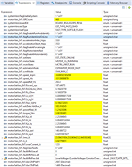
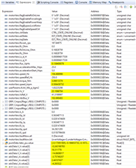
Oddly USER_MOTOR1_FORCE_DELTA_ A , USER_MOTOR1_ALIGN_DELTA_A have no associated function or variable being defined in user_mtr1.h is broken link to fast_full_lib.lib. No compiler warnings ABI or COF issues though this seems to be COF library build for ABI build project settings?
Why both motors work ok in SDK4.0 but not in MCSDK? When the motor current is <1A small motor starts and runs to reference target trajectory speed but big motor stay in forced angle open loop speed 1Hz.? Please suggest some user_mtr1.h setting to help the kgm^2 rotor mass of the big motor, many EV class range >63lbs inertia. Also tied UMCSDK with several M1.Kp_spd values, e.g. 148.xxx, 48.xxx to 0.48xxxx still no change to accelerate to reference trajectory speed.
MCSDK big motor user_mtr1.h SDK4.0 big motor user.h settings
Settings SDK4.0 that are similar but do not work UMCSDK same motor, more current same issue does not accelerate to reference trajectory speed.
#define USER_MOTOR1_TYPE MOTOR_TYPE_PM
#define USER_MOTOR1_NUM_POLE_PAIRS (18)
#define USER_MOTOR_SPEED_REF_HZ (265) // Set Trajectory Speed
#define USER_MOTOR1_Rr_Ohm (NULL)//ACIM only
//Cust-INV: DCINV 0.16828759, DRV8320RS 0.155892089
#define USER_MOTOR1_Rs_Ohm (0.16828759)
//Cust-INV: 0.000986817526, DRV8320RS 0.000890934956
#define USER_MOTOR1_Ls_d_H (0.000896817526)
#define USER_MOTOR1_Ls_q_H (0.000896817526)
//Cust-INV:0.138790429
#define USER_MOTOR1_RATED_FLUX_VpHz (0.138790429)
#define USER_MOTOR1_MAGNETIZING_CURRENT_A (NULL)//ACIM only
#define USER_MOTOR1_RES_EST_CURRENT_A (5.0f) // 10-30% of rated current HV36/8.2A, unloaded 5.0/100v
#define USER_MOTOR1_IND_EST_CURRENT_A (-4.5f) // 10-30% of rated current(LS) HV36:-4.5
#define USER_MOTOR1_MAX_CURRENT_A (5.65f) // Saturation current(Peak) HV36:5.6
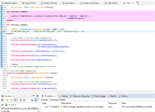
#define USER_MOTOR1_FLUX_EXC_FREQ_Hz (60.0f) // MotorID 60 Hz for [1 uH < Lphase < 10 uH]
// MotorID 20 Hz for [10 uH < Lphase < 1000 uH]
// Number of lines on the motor's quadrature encoder
#define USER_MOTOR1_NUM_ENC_SLOTS (NULL)
#define USER_MOTOR1_INERTIA_Kgm2 (0.352838295721)
#define USER_MOTOR1_FREQ_NEARZEROLIMIT_Hz (2.0f) // Hz
#define USER_MOTOR1_RATED_VOLTAGE_V (250.0f)
#define USER_MOTOR1_RATED_SPEED_KRPM (3.5f)
#define USER_MOTOR1_FREQ_MIN_HZ (2.0f) // Hz
#define USER_MOTOR1_FREQ_MAX_HZ (1350.0f) // Hz 720Hz*60/18=2400rpm, Hz-suggested to set to 120% of rated motor frequency
#define USER_MOTOR1_FREQ_LOW_HZ (65.0f) // Hz 65Hz - suggested to set to 10% of rated motor frequency
#define USER_MOTOR1_FREQ_HIGH_HZ (650.0f) // Hz 650Hz*60/18=2166rpm: suggested to set to 100% of rated motor frequency
#define USER_MOTOR1_VOLT_MIN_V (85.0f) // Volt
#define USER_MOTOR1_VOLT_MAX_V (186.0f) // Volt
#define USER_MOTOR1_FORCE_DELTA_A (0.55f) // A
#define USER_MOTOR1_ALIGN_DELTA_A (0.25f) // A
#define USER_MOTOR1_FLUX_CURRENT_A (5.25f) // !A
#define USER_MOTOR1_ALIGN_CURRENT_A (5.0f) // !A
#define USER_MOTOR1_STARTUP_CURRENT_A (7.25f) // !A
#define USER_MOTOR1_TORQUE_CURRENT_A (2.65f) // !A
#define USER_MOTOR1_OVER_CURRENT_A (12.8f) // !A
#define USER_MOTOR1_BRAKE_CURRENT_A (1.0f) // A
#define USER_MOTOR1_BRAKE_TIME_DELAY (12000U) // 60s/5ms
#define USER_MOTOR1_SPEED_START_Hz (5.0f)
#define USER_MOTOR1_SPEED_FORCE_Hz (15.0f)
#define USER_MOTOR1_ACCEL_START_Hzps (5.0f) // !Hz
#define USER_MOTOR1_ACCEL_MAX_Hzps (25.0f) // !Hz
Change settings universal MCSDK motor still remains ±1Hz does not accelerate to reference trajectory speed, even when less current motor still starts up spins only 1Hz.
#define USER_MOTOR1_FREQ_NEARZEROLIMIT_Hz  (2.0f)       // Hz

#define USER_MOTOR1_RATED_VOLTAGE_V        (250.0f)
#define USER_MOTOR1_RATED_SPEED_KRPM       (3.5f)

#define USER_MOTOR1_FREQ_MIN_HZ            (2.0f)       // Hz
#define USER_MOTOR1_FREQ_MAX_HZ            (1350.0f)    // Hz 720Hz*60/18=2400rpm, Hz-suggested to set to 120% of rated motor frequency

#define USER_MOTOR1_FREQ_LOW_HZ            (65.0f)     // Hz 65Hz - suggested to set to 10% of rated motor frequency
#define USER_MOTOR1_FREQ_HIGH_HZ           (650.0f)    // Hz 650Hz*60/18=2166rpm: suggested to set to 100% of rated motor frequency

#define USER_MOTOR1_VOLT_MIN_V             (85.0f)      // Volt
#define USER_MOTOR1_VOLT_MAX_V             (186.0f)     // Volt

#define USER_MOTOR1_FORCE_DELTA_A          (0.55f)      // A
#define USER_MOTOR1_ALIGN_DELTA_A          (0.25f)      // A
#define USER_MOTOR1_FLUX_CURRENT_A         (1.75f)      // !A
#define USER_MOTOR1_ALIGN_CURRENT_A        (4.0f)       // !A
#define USER_MOTOR1_STARTUP_CURRENT_A      (3.55f)      // !A
#define USER_MOTOR1_TORQUE_CURRENT_A       (1.65f)      // !A
#define USER_MOTOR1_OVER_CURRENT_A         (12.0f)      // !A

#define USER_MOTOR1_BRAKE_CURRENT_A        (1.0f)       // A
#define USER_MOTOR1_BRAKE_TIME_DELAY       (12000U)     // 60s/5ms
#define USER_MOTOR1_SPEED_START_Hz         (15.0f)
#define USER_MOTOR1_SPEED_FORCE_Hz         (25.0f)
#define USER_MOTOR1_ACCEL_START_Hzps       (35.0f)      // !Hz
#define USER_MOTOR1_ACCEL_MAX_Hzps         (55.0f)      // !Hz
SDK4.0 user settings work ok for bigger motor to startup but why not in MCSDK?
	USER_MOTOR_TYPE				=	  1, // MOTOR_TYPE_PM,

	USER_MOTOR_NUM_POLE_PAIRS   =     18, // HV36:18pp

	USER_MOTOR_Rr_Ohm           =     0, //ACIM only

	USER_MOTOR_Rs_Ohm           =     0.16828759,
	//HV36: DCINV 0.16828759, DRV8320RS 0.155892089

	USER_MOTOR_Ls_d_H           =    0.000896817526,
	//HV36: INV 0.000986817526, DRV8320RS 0.000890934956

	USER_MOTOR_Ls_q_H           =    0.000896817526,
	//HV36: INV 0.000986817526, DRV8320RS 0.000890934956

	USER_MOTOR_RATED_FLUX_VpHz  =      0.138790429,
	//HV36:0.138790429
	USER_MOTOR_MAGNETIZING_CURRENT_A = 0, //ACIM only
	USER_MOTOR_RES_EST_CURRENT_A   =    5.0,  // 10-30% of rated current HV36/8.2A, unloaded 5.0/100v
	USER_MOTOR_IND_EST_CURRENT_A   =   -4.5, // 10-30% of rated current(LS) HV36:-4.5
	USER_MOTOR_MAX_CURRENT_A       =    5.6, // Saturation current(Peak) HV36:5.6
	USER_MOTOR_FLUX_EXC_FREQ_Hz    =   60.0, // MotorID 60 Hz for [1 uH < Lphase < 10 uH]
						 // MotorID 20 Hz for [10 uH < Lphase < 1000 uH]

        USER_MOTOR_INERTIA_EN	    =	(1), //1:true, 0:false

	USER_MOTOR_INERTIA_Kgm2     =   0.325505192710553,

	USER_MOTOR_NUM_ENC_SLOTS     =      71, // Number of lines on the motor's quadrature encoder

	USER_MOTOR_FREQ_MIN_HZ       =      2.0,  // Hz
	USER_MOTOR_FREQ_MAX_HZ       =      780.0, // 720Hz*60/18=2400rpm, Hz-suggested to set to 120% of rated motor frequency

	USER_MOTOR_FREQ_LOW_HZ       =       65.0, // 65Hz - suggested to set to 10% of rated motor frequency
	USER_MOTOR_FREQ_HIGH_HZ      =      650.0, // 650Hz*60/18=2166rpm: suggested to set to 100% of rated motor frequency

	USER_MOTOR_VOLT_MIN_V        =       60.0,  // Volt - suggested to set to 15% of rated motor voltage
	USER_MOTOR_VOLT_MAX_V        =      160.0,  // Volt - suggested to set to 100% of rated motor voltage

	HAL_PWM_DBRED_CNT			 =	   	20, // PWM Deadband RED register x 10 nanosecond SYSCLK periods
	HAL_PWM_DBFED_CNT			 =	   	20, // PWM Deadband FED register x 10 nanosecond SYSCLK periods
	HAL_PWM_DB_CNT			 	 =	   	20, // DRV 8320RS gate driver deand band SPI register value.

	USER_PWM_FREQ_kHz     		 =     	20.0, // EPWM module PRD clock frequency for DC inverter modulation.

    //! \brief Defines the maximum P2P current at the AD converter
    USER_ADC_FULL_SCALE_CURRENT_A   =   82.0; //PGA 42.843, INA240A1:78-82.0