This thread has been locked.

If you have a related question, please click the "Ask a related question" button in the top right corner. The newly created question will be automatically linked to this question.

TMS320F280025C: Issues with manual control of CS pin in SPI when using driverlib functions

Part Number: TMS320F280025C
Other Parts Discussed in Thread: SYSCONFIG

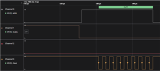
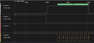
I have configured SPI in 3 pin mode using sysconfig. I selected the use case as custom and used only POCI, PICO and CLK pins. However, when I manually make the CS pin low, and use any driverlib function to read or write SPI data, there's an initial clock pulse that makes the data read erroneous. This pulse is also present in 4 pin mode, but in that mode the CS pin is pulled low only after that initial pulse is over. How can I stop this from happening?

4 pin mode

3 pin mode

  • This is really odd. First guess is that the clock glitch is due to SPI_CLK pin pinmux configuration happening right before the SPI transfer starts, but all the pinmux configuration is done by the sysconfig generated code in board.c when Board_init() is called, which is usually long before your application starts running. Unless you are calling SPI_init() directly? Can you share the snippet of code that leads to this issue? 

  • Dear Gus,

    Sure, here it is.

    //
    // Included Files
    //
    #include "driverlib.h"
    #include "device.h"
    #include "board.h"
    //#include "f28x_project.h"
    
    //
    // Main
    //
    
    void main(void)
    {
        // Device Initialization
        Device_init();
    
        //
        // Initializes PIE and clears PIE registers. Disables CPU interrupts.
        //
        Interrupt_initModule();
    
        //
        // Initializes the PIE vector table with pointers to the shell Interrupt
        // Service Routines (ISR).
        //
        Interrupt_initVectorTable();
    
        Board_init();
    
        //
        // Enable Global Interrupt (INTM) and realtime interrupt (DBGM)
        //
        EINT;
        ERTM;
    
        for(;;)
        {
            GPIO_writePin(SPI_LTC_CS, 0);
            SPI_receiveByte(SPI_LTC_BASE, 0xFF);
            SysCtl_delay(0.1*100000000/5);//delay seconds * 100*10E6/5
            GPIO_writePin(SPI_LTC_CS, 1);
            SysCtl_delay(0.1*100000000/5);
        }
    
    
    }
    
    //
    // End of File
    //
    

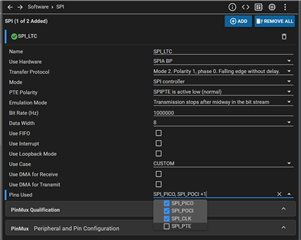
    Here's the sysconfig settings for SPI peripheral in 3 pin mode.

  • Can you replace SPI_receiveByte() in your code with the following? Let me know if there is any difference in behavior. 

        //
        // Write to SPI Transmit buffer
        //
        SPI_writeDataBlockingNonFIFO(SPI_LTC_BASE, 0xFF << (8));
    
        //
        // Read SPI Receive buffer
        //
        rxData = SPI_readDataBlockingNonFIFO(SPI_LTC_BASE);

  • I tried it. Now the initial clock pulse is gone. I guess I have to stay away from certain driverlib functions.

    When looped externally, data is also read correctly. However, the logic analyzer can decode the data only in mode 2 (CPOL = 1, CPHA = 0). But the SPI peripheral is set to operate in mode 3. Following is the trace when the logic analyzer is set to mode 3.

  • I think I found the issue for the initial clock pulse. In driverlib functions SPI_pollingNonFIFOTransaction() and SPI_pollingFIFOTransaction(), the SPI module is disabled and re-enabled to set the character length. This is carried onto the macros like SPI_receiveByte() as well, which are defined using those functions.

  • I think I found the issue for the initial clock pulse. In driverlib functions SPI_pollingNonFIFOTransaction() and SPI_pollingFIFOTransaction(), the SPI module is disabled and re-enabled to set the character length. This is carried onto the macros like SPI_receiveByte() as well, which are defined using those functions.

    Yes, this is what I observed as well. I will file this as a bug.

    However, the logic analyzer can decode the data only in mode 2 (CPOL = 1, CPHA = 0). But the SPI peripheral is set to operate in mode 3. Following is the trace when the logic analyzer is set to mode 3.

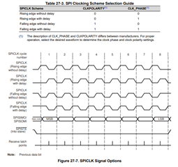
    The SPI mode is not an industry standard. You'll find that different vendors use different definitions for SPI mode. Please refer to the SPI chapter in the F28002x TRM to understand the behavior expected based on the CLKPOLARITY and CLK_PHASE settings and configure the logic analyzer accordingly.

  • Ok. Thank you for the support Gus.