This thread has been locked.
If you have a related question, please click the "Ask a related question" button in the top right corner. The newly created question will be automatically linked to this question.
Hello,
We are facing a problem of distortion in the sinusoidal output voltage of half bridge inverter using ePWM module on F280049.
A sinusoidal PWM is generated with complementary outputs of ePWM2A and ePWM2B outputs. Following are the code related snippets:
/*------------------------------------------------------------------------------------------------------------------------------------------*/
/*--PWM initialization--*/
EALLOW;
// Time Base SubModule Registers
EPWM_setPeriodLoadMode(base,EPWM_PERIOD_SHADOW_LOAD);
EPWM_setTimeBaseCounterMode(base,EPWM_COUNTER_MODE_UP_DOWN);
EPWM_disablePhaseShiftLoad(base);
EPWM_setClockPrescaler(base,EPWM_CLOCK_DIVIDER_1,EPWM_HSCLOCK_DIVIDER_1);
EPWM_setTimeBasePeriod(base,pwm_period_ticks);//Set PWM period
EPWM_setTimeBaseCounter(base,0);
EPWM_setPhaseShift(base,0);
// Counter Compare Submodule Registers
EPWM_setCounterCompareValue(base,EPWM_COUNTER_COMPARE_A,0);
EPWM_setCounterCompareValue(base,EPWM_COUNTER_COMPARE_B,0);
EPWM_setCounterCompareShadowLoadMode(base,EPWM_COUNTER_COMPARE_A,EPWM_COMP_LOAD_ON_CNTR_ZERO);
EPWM_setCounterCompareShadowLoadMode(base,EPWM_COUNTER_COMPARE_B,EPWM_COMP_LOAD_ON_CNTR_ZERO);
// set as immediate mode
EPWM_disableCounterCompareShadowLoadMode(base,EPWM_COUNTER_COMPARE_A);
EPWM_disableCounterCompareShadowLoadMode(base,EPWM_COUNTER_COMPARE_B);
// Action Qualifier SubModule Registers
// to start don't configure the PWM to do anything
HWREGH(base + EPWM_O_AQCTLA) =0 ;
HWREGH(base + EPWM_O_AQCTLB) =0 ;
EPWM_setActionQualifierAction(base, EPWM_AQ_OUTPUT_A ,
EPWM_AQ_OUTPUT_HIGH, EPWM_AQ_OUTPUT_ON_TIMEBASE_DOWN_CMPA);
EPWM_setActionQualifierAction(base, EPWM_AQ_OUTPUT_A ,
EPWM_AQ_OUTPUT_LOW, EPWM_AQ_OUTPUT_ON_TIMEBASE_UP_CMPA);
// Complementary PWMs, PWMA source for OUTA and OUTB
EPWM_setDeadBandCounterClock(base,EPWM_DB_COUNTER_CLOCK_FULL_CYCLE);
EPWM_setRisingEdgeDelayCount(base,pwm_dbred_ticks);
EPWM_setFallingEdgeDelayCount(base,pwm_dbred_ticks);
EPWM_setDeadBandDelayMode(base,EPWM_DB_RED,true);//Register DBCTL bits OUT_MODE; S1=1-> RED in A signal path
EPWM_setDeadBandDelayMode(base,EPWM_DB_FED,true);//Register DBCTL bits OUT_MODE; S0=1-> FED in B signal path
EPWM_setRisingEdgeDeadBandDelayInput(base,EPWM_DB_INPUT_EPWMA);//Register DBCTL bits IN_MODE; S4=0 -> input signal ePWMA for RED and FED
EPWM_setFallingEdgeDeadBandDelayInput(base,EPWM_DB_INPUT_EPWMA);//Reg DBCTL bit DEDB_MODE(S8)=0; IN_MODE S5=0-> input signal ePWMA for FED
EPWM_setDeadBandDelayPolarity(base,EPWM_DB_FED,EPWM_DB_POLARITY_ACTIVE_LOW);//Reg DBCTL bit POLSEL(S3)=1 ->OUTB inverted
EPWM_setDeadBandDelayPolarity(base,EPWM_DB_RED,EPWM_DB_POLARITY_ACTIVE_HIGH);//Reg DBCTL bit POLSEL(S2)=0->OUTA not inverted
/*--PWM generation in ISR in open loop--*/
invDutyPU = (spll1.sine) * invVoRefInst * 0.8;
invDutyPU= (invDutyPU>(float)(0.8))?(float)(0.8):invDutyPU;
invDutyPU= (invDutyPU<(float)(-0.8))?(float)(-0.8):invDutyPU;
EPWM_setCounterCompareValue(INV_PWM_BASE, EPWM_COUNTER_COMPARE_A, ( (uint16_t) (pwmDutyVar + (pwmDutyVar*invDutyPU) ) ));//pwmDutyVar is half the PWM period count
/*------------------------------------------------------------------------------------------------------------------------------------------*/
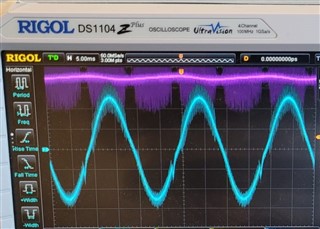
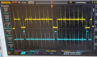
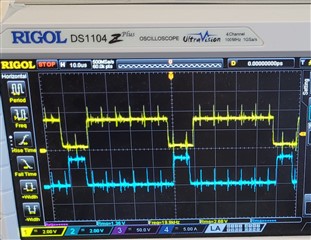
Please see the output voltage waveform generated using above code (Blue waveform in the attached image). There appears a small distortion in the waveform in the negative half cycle. To be sure that the distortion is due to PWM generated from PWM module, we exchanged the inverter transistor driver outputs keeping the inputs same. Then the distortion appears in the positive half cycle.
Can you please help us to understand if this is related to PWM generation as we suspect.
With regards,
Vijay
Hi Vijay,
Would it be possible for you to obtain a scope shot of your PWM outputs directly? Perhaps we can find some glitch our problem in the PWM outputs that doesn't match the expected output based on your configuration code.
Thank you,
Luke
Hello Luke,
Please see the PWM output waveforms of PWMA and PWMB from microcontroller in the image below.
With regards,
Vijay
Thanks Vijay,
Your PWM outputs appear to be very noisy. This may be the cause of the glitch in the sine wave output. There is a very large spike in the beginning of your PWM period, during the positive duty cycle. Can you determine what may be the cause of this noise?
Thank you,
Luke
Hello Luke,
We will investigate and get rid of the glitches. In the meanwhile, we have added a small filter at the gate driver inputs to filter out the noise. Please see below the waveforms at the gate driver input pins. The noise is minimized, but the problem of distortion in the inverter output still remains.
Hi Vijay,
There doesn't seem to be anything wrong with PWM output in the image you just sent. If you can point out something specific with the PWM output that seems wrong, I can assist you with finding the correct configuration. However the problem seems to be in the inverter itself. I will have this thread assigned to another expert who can better assist you.
In the meantime, can you send an updated scope shot of your inverter output after applying the filter?
Thank you,
Luke
Hello Luke,
It would be really helpful if some one from your side can guide on this topic. As said in my initial message, the distortion changes from negative half cycle to positive half cycle when the PWM outputs driving the transistors are interchanged. If there is a problem in inverter and not in PWM generation, then the distortion should not change from positive half cycle to negative half cycle when the PWM outputs are interchanged.
With regards,
Vijay
Hello Vijay,
To help try and find an expert who can help properly, did you refer to any reference design or C2000 libraries (such as digital power or motor control), when creating your system?
Best regards,
Omer Amir
Hello Omer,
We did review design from Digital Power SDK as a reference for a similar working concept (\DigitalPowerSDK\C2000Ware_DigitalPower_SDK_3_01_00_00\solutions\tidm_hv_1ph_dcac), but system we have (both hardware and software) is our own design.
The design referred above is a full bridge inverter rated for 600VA while the inverter we have is half bridge inverter rated for 3000VA.
With regards,
Vijay Limaye
Hello Navaneeth,
The distortion we observed is on a light resistive load. If the problem is with the load, why would the distortion change from negative half cycle tp positive half cycle when the driver outputs are interchanged?
With regards,
Vijay
Hi Vijay,
I will be trying out your code on F28004x control card and will let you know. The PWM waveforms are distorting at regular intervals (7.5us). Either random code might be causing this (or) it could be from hardware.
Please wait for 2 days for my response.
Thanks & Regards,
Uttam
Hello Uttam,
Thank you for your help. As discussed earlier, to verify if the distortion in the inverter output is due to distortion in the PWM, we added a RC filter before the driver input. Please see the driver input PWM waveforms with filter in the earlier reply. The distortion in the inverter remains as it is even with filter cleaned PWM waveforms.
With regards,
Vijay
Hi Vijay,
The code looks good to me.
May I know if the C2000 device is on the hardware(base board) or using the controlCARD in your application. Incase a controlcard we can run the code without base board and see if the PWMs are generated correctly or not?
Best,
Uttam
Hi Vijay,
May I know if you are still seeing the issue?
Thanks & Regards,
Uttam
Hello Uttam,
The C2000 device is on our own custom designed board. The issue is still there as it was.
With regards,
Vijay
Vijay,
After you added the RC filters across the PWMs could you share the output current waveform? In order to further debug this,
1. This could be due to cross coupling on HW, let me know if you are comfortable in sharing the HW design with us for expert review purpose.
2. Is it possible for you to run the same open loop code on any launchpad/control card then probe PWM outputs to confirm the SW has any unintential interrupts causing it. (or) I can take a look at the code and try this from my end as well.
Best Regards,
Uttam
Hello Uttam,
I will look into the possibility of running this code from controlCard and check the outcome. That should clarify if the problem is with the hardware or software.
With regards,
Vijay
Hello Uttam,
We tested the same code using F280049C controlCard. Please see attached the snapshots - the same distortion appears using PWM outputs from controlCard.
With regards,
Hi Vijay,
Thanks for your testing it on Control card. Could you please probe PWM outputs from control card and share the snipshots here.
Best Regards,
Uttam
Hello Uttam,
Please see the controlCard PWM outputs snapshot.
With regards,
Vijay
Hi Vijay,
I assume this might be due to some external code running in the backgound. Could you share the code with me so I can run it on control card, to better assist you. In the mean time, I can ask other experts as well.
Thanks & Regards,
Uttam
Hello Uttam,
Please see below the ISR code for inverter PWM.
dcBusVoltageSamplePU = ((float32_t) (READ_DC_BUS_AD_RESULT2))*ADC_PU_SCALE_FACTOR;
offset1V65SamplePU = ((float32_t) (READ_OFFSET1V65_AD_RESULT))*ADC_PU_SCALE_FACTOR;
inverterOut.i = ( (((float32_t)(READ_OP_CUR_AD_RESULT))*ADC_PU_SCALE_FACTOR) - (offset1V65PU) )*2.0;
inverterOut.v = ( (((float32_t)(READ_INV_VOLT_AD_RESULT))*ADC_PU_SCALE_FACTOR) - (offset1V65PU) )*2.0;
inputVoltageLE.v = ( (((float32_t)(READ_IP_VOLT_LE_AD_RESULT))*ADC_PU_SCALE_FACTOR) - offset1V65PU )*2.0;
// closed voltage and current Loop
invVoRefInst = sinf(0.007853981634 * sampleCount) * invVoRef * 0.8;
voltage_error= invVoRefInst - inverterOut.v;
gv_out= DCL_runDF22_C1(&gv_pr1, voltage_error)
+ DCL_runDF22_C1(&gv_r3, voltage_error)
+ DCL_runDF22_C1(&gv_r5, voltage_error)
+ DCL_runDF22_C1(&gv_r7, voltage_error);
gv_out= (gv_out>(float)(0.8))?(float)(0.8):gv_out;
gv_out= (gv_out<(float)(-0.8))?(float)(-0.8):gv_out;
gv_lead_lag_out= DCL_runDF22_C1(&gv_lead_lag, gv_out);
gv_lead_lag_out= (gv_lead_lag_out>(float)(0.8))?(float)(0.8):gv_lead_lag_out;
gv_lead_lag_out= (gv_lead_lag_out<(float)(-0.8))?(float)(-0.8):gv_lead_lag_out;
invIoRefInst =(gv_lead_lag_out);
gi_out= DCL_runDF22_C1(&gi, (invIoRefInst - inverterOut.i));
gi_out= (gi_out>(float)(0.8))?(float)(0.8):gi_out;
gi_out= (gi_out<(float)(-0.8))?(float)(-0.8):gi_out;
invDutyPU= invVoRefInst;
if((enable) && (onOff) )
{
INV_PWMH_OFF = 0x0;
INV_PWML_OFF = 0x0;
if(invVoRef < 1.0)
{
invVoRef+= INV_VO_REF_INC_PU;
}
else
{
invVoRef = 1.0;
}
}
else
{
INV_PWMH_OFF = 0x01;
INV_PWML_OFF = 0x01;
invVoRef = 0.0;
}
invDutyPU= (invDutyPU>(float)(0.8))?(float)(0.8):invDutyPU;
invDutyPU= (invDutyPU<(float)(-0.8))?(float)(-0.8):invDutyPU;
//Inverter PWM update
INV_PWM_CMPA = (uint16_t) ((float)(pwmDutyVar) + ((float)(pwmDutyVar)*invDutyPU) );
VIjay,
Can you confirm when you used ONLY control card while probing for EPWM outputs. Your HW is not connected to half bridge inverter is that correct?
Thanks & Regards,
Uttam
Hello Uttam,
Following was the set up when the EPWM outputs of controlCard were probed:
The EPWM outputs from controlCard were connected to inputs of driver ICs (ISO5451). The isolated outputs of driver ICs were connected to inverter. However, the inverter power circuit was in off condition i.e. the inverter DC bus was not powered.
With regards,
Vijay
Hi Vijay,
I see,
Could you scope the waveform on HSEC just from control card without giving it to drivers on HW.
Ideally, without the power circuit it should show the same results. But I want to eliminate the possibility of GND bouces from the main board if any.
Thanks & Regards,
Uttam
Hello Uttam,
Please see the controlCard PWM outputs now disconnected from drivers and also with the power circuit in OFF condition.
With regards,
Vijay
Vijay, the above code looks okay to me.
It's challenging to pinpoint the problem without being able to run the code. Please send the entire code if possible via email shared to you.
Thanks,
Uttam
Hello Uttam,
Currently not in office for few days, will send the code shortly
With regards,
Vijay
Hello Uttam,
I tried sending the code to the email id shared by you. But I get delivery failure notification.
I will try again later.
With regards,
Vijay
Hello Uttam,
I again tried sending the code to the email id shared by you. But I get delivery failure notification.
Request you to send me an e mail from the id where the code needs to be sent so that I can reply to that email.
With regards,
Vijay
Hi Vijay,
I sent a private message over to you. Please send to the same email shared.
Thanks & Regards,
Uttam
Hi Vijay,
Closing this E2E thread. As our conversations are moved to email.
Thanks & Regards,
Uttam