This thread has been locked.

If you have a related question, please click the "Ask a related question" button in the top right corner. The newly created question will be automatically linked to this question.

TMS320F280037C: Motorcontrol SDK: no PWM output on initial configuration

Part Number: TMS320F280037C
Other Parts Discussed in Thread: C2000WARE

Hello,

I have some custom hardware being controlled by a F280037C using the Universal Motor Control lab.

Currently, the code gets to the following loop:

        // write the PWM compare values
        HAL_writePWMData(obj->halMtrHandle, &obj->pwmData);

        // enable the PWM
        HAL_enablePWM(obj->halMtrHandle);

        for(offsetCnt = 0; offsetCnt < 32000; offsetCnt++)
        {
            // clear the ADC interrupt flag
            ADC_clearInterruptStatus(MTR1_ADC_INT_BASE, MTR1_ADC_INT_NUM);

            while(ADC_getInterruptStatus(MTR1_ADC_INT_BASE, MTR1_ADC_INT_NUM) == false);

            HAL_readMtr1ADCData(&obj->adcData);

            if(offsetCnt >= 2000)       // Ignore the first 2000 times
            {
                // Offsets in phase current sensing

where it is forever stuck waiting for an ADC callback:

static inline bool
ADC_getInterruptStatus(uint32_t base, ADC_IntNumber adcIntNum)
{
    //
    // Check the arguments.
    //
    ASSERT(ADC_isBaseValid(base));
    //
    // Get the specified ADC interrupt status.
    //
    return((HWREGH(base + ADC_O_INTFLG) & (1U << (uint16_t)adcIntNum)) != 0U);
}

The PWM is supposed to trigger the SOC to take a reading, and the ADC should raise this interrupt, incrementing 'offsetCnt'.

However, 'offsetCnt' never increments.

I am fairly certain I have correctly modified the lab to allow my hardware to function, but here I am.

I can force an ADC callback by setting 'AdcbRegs.ADCSOCFRC1.SOC3' to 1, forcing one of the ADC's to take a reading. 'offsetCnt' increments by 1 when I do this.

Here are the EPWM registers during this loop:

EPwm4Regs.TBPRD	Register	0x0FA0		
EPwm4Regs.TZFLG	Register	0x0006		
EPwm2Regs.TZFLG	Register	0x0006		
EPwm3Regs.TZFLG	Register	0x0006		

Any tips on where I should be looking? I am pouring over the 'Building Custom Board' section of the 'Motor Control SDK Universal Project and Lab' right now.

I feel like I almost have this working...

  • Hi,

    It must be the ADC interrupt flag never gets set. Have you made changes to hal.h file to match your PWMs / ADCs being used? Can you check the respective ADC registers in CCS while running.

    Best,

    Kevin

  • I have changed the ADC and GPIO pins significantly. I have been doing so, keeping the motor control structure intact, while pointing the ADCs, CMPSS, and PWM modules to their new configurations. I am still combing through my code to check for errors.

    I think my bigger issue is PWM is not being generated. Without the PWM module activating, no interrupt is sent to trigger the ADC to take a reading.

    I loaded an example lab (cla_ex4_pwm_control) and a PWM signal is successfully generated, viewable on my oscilloscope.

    However, I do not see a PWM signal is generated in the modified Universal Motor Control lab, especially when one should be generated at this point in code. 

    I tried writing a standalone PWM signal and have had no luck so far.

    I will take a closer look at my ADC registers tomorrow. For the moment, I have only been watching the data they capture, or lack thereof (all zeros, no callback) except when forcing an individual SOC to take a reading.

  • Hello Aric,

    Were you able to determine any additional information from the ADC registers? If not, I have a few specific questions that may help us track down where the issue is. These questions are sorted in the order of priority, with the first question being related to what I believe is most likely to be causing this:

    1. Can you tell me the contents of the following ePWM registers, viewable in the CCS debug Registers or Expressions window?
      1. EPWMx registers, where X is the PWM number defined in hal.h as MTR1_PWM_INT_BASE
        1. ETSEL configuration register
        2. ETFLG status register
        3. TBCTL configuration register
    2. Can you tell me the contents of the following ADC registers, viewable in the CCS debug Registers or Expressions window?
      1. ADCA Registers
        1. ADCSOCxCTL configuration register, where X is the SOC number defined in hal.h as MTR1_ADC_INT_SOC (Should be 4 by default)
        2. ADCINTSEL1N2 configuration register
    3. Can you tell me the contents of the following variable, viewable in the CCS debug Expressions window?
      1. motorVars_M1.faultMtrNow.all

    The relevant ePWM handle in the Universal Motor Control Lab should be pwmHandle[0], if you feel that you need that to help track down any information.

    Regards,
    Jason Osborn

  • Hello Jason,

    Sorry the forums went down and I was busy thoroughly examining all the configurations.

    • Can you tell me the contents of the following ePWM registers, viewable in the CCS debug Registers or Expressions window?
      1. EPWMx registers, where X is the PWM number defined in hal.h as MTR1_PWM_INT_BASE
        1. ETSEL configuration register
        2. ETFLG status register
        3. TBCTL configuration register
    • Can you tell me the contents of the following ADC registers, viewable in the CCS debug Registers or Expressions window?
      1. ADCA Registers
        1. ADCSOCxCTL configuration register, where X is the SOC number defined in hal.h as MTR1_ADC_INT_SOC (Should be 4 by default)
        2. ADCINTSEL1N2 configuration register

    I managed to get the PWM triggering the ADCs. I did end up correcting settings of the EPWM and ADC's, which likely could have been caught by checking those registers.

    Can you tell me the contents of the following variable, viewable in the CCS debug Expressions window?
    1. motorVars_M1.faultMtrNow.all

    So I have been checking this expression a lot. Another  weird problem was occurring, the ADCs would read but would saturate either to 0 or to 4095, which throws the motorVars_M1.faultMtrNow.overVoltage bit and shuts down the PWMs

    Here is my procedure:

    (EDIT: fixed code ADC code init snipped, was from 'adc_ex1_soc_epwm', not the Universal Motor Control lab; got got caught in a ctrl + H, but the setup is similar)

    The ADC was configured (by default) to be internally regulated and to measure to 3.3V VREFHI:

    void HAL_setupADCs(HAL_Handle handle)
    {
        HAL_Obj *obj = (HAL_Obj *)handle;
        SysCtl_delay(100U);
        ADC_setVREF(obj->adcHandle[0], ADC_REFERENCE_INTERNAL, ADC_REFERENCE_3_3V);
        ADC_setVREF(obj->adcHandle[1], ADC_REFERENCE_INTERNAL, ADC_REFERENCE_3_3V);
        ADC_setVREF(obj->adcHandle[2], ADC_REFERENCE_INTERNAL, ADC_REFERENCE_3_3V);
    ...

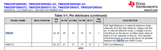
    On my hardware, VREFLO and VREFHI have a capacitor between them, which appears to be the correct hardware configuration as per the F28003x datasheet:

    However, when I measure either side of the VREFHI or VREFLO capacitor to ground, it measures 1.335V and the ADC saturates my measurement to 4095.

    Then I tried something a little weird: I soldered a wire from the VREFLO side to the ground plane, and the ADC now functions 'perfectly'.

    VREFHI measure 1.65V to ground and VREFLO is obviously now grounded.

    And my measurements are now correctly reading my test inputs.

    Except this seems to be wrong... the VREFLO should be tied to ground internally.

    I don't see a way to change the voltage reference itself. The 'ADC_setVREF()' command is tied to each of the 3 ADC modules, not to the voltage reference pin configuration necessarily...

    What could be the issue? I am using the 64PM chip (not PMQ, which has the VREGENZ pin for selecting an external regulator).

    The model stamped onto the chip is "280037CSPM"

    (edit: PMQ, not PMZ)

  • Aric,

    Just to be certain, this is the setup/similar to the setup of your VREFHI/VREFLO pins, correct?

    Image taken from the F280039C ControlCard schematic document in C2000Ware. Note that in this schematic, U1 is the F280039C, which is the yellow block in the screenshot.

    Additionally, if that is what your system looks like, what are the contents of the Analog Subsystem registers ANAREFCTL[ANAREF2P5SEL] and ANAREFCTL[ANAREFSEL] ?

    Regards,
    Jason Osborn

  • The original setup only had the 2.2uF capacitor between VREFHI and VREFLO.

    The modified setup that has working ADC measurements is similar to the system.

    I will check those registers right away...

  • Looks like it is correctly set to internal reference at 3.3V:

    All zeros on the register while the program is running, which is internal 3.3V reference mode.

    Odd that the ground reference is needed? I will verify with future boards I set up.

    I have more questions but I think this one is resolved: everything seems to working.

    PWM works with the ADC, just needed to be very precise with settings, and debug this weird hardware issue.