This thread has been locked.
If you have a related question, please click the "Ask a related question" button in the top right corner. The newly created question will be automatically linked to this question.
Hello everyone,
I'm currently trying to do the following :
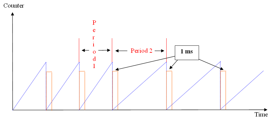
The point is I want to always have a 1ms high-level output after the counter reached the period and that period is variable.
I tried to set the ePWM period (TBPRD) equal to the period of Timer2 which is set up to produce the desired frequency :
void tim2_init(int regime) { float period; static int initialized = 0; if (regime < 300) { initialized = 0; // Initialisation � faire CpuTimer2Regs.TCR.bit.TSS = 1; // Stop le timer 2 } else { period = 120*(1000000/(float)regime); // Lance le timer en mode auto-reload if(initialized == 0) { // Configure CPU-Timer 0 to interrupt every (period/1000000) second: // 80MHz CPU Freq, period (in uSeconds) ConfigCpuTimer(&CpuTimer2, 80, period); // Initialize the EPWM module : InitEPwmTimer(); initialized = 1; } Freq_ind = 1000000/period; } }
void InitEPwmTimer(void) { EALLOW; SysCtrlRegs.PCLKCR0.bit.TBCLKSYNC = 0; // Stop all the TB clocks EDIS; // Setup Sync EPwm8Regs.TBCTL.bit.SYNCOSEL = 0; // Pass through // Allow each timer to be sync'ed // EPwm8Regs.TBCTL.bit.PHSEN = 1; // EPwm8Regs.TBPHS.half.TBPHS = 200; EPwm8Regs.TBPRD = CpuTimer2Regs.PRD.all; // P�riode de l'ePWM = p�riode du Timer 2 EPwm8Regs.TBCTL.bit.CTRMODE = 0; // Count up // EPwm8Regs.ETSEL.bit.INTSEL = 1; // Enable INT on Zero event // EPwm8Regs.ETSEL.bit.INTEN = 1; // Enable INT // EPwm8Regs.ETPS.bit.INTPRD = 1; // Generate INT on 1st event EPwm8Regs.AQCTLA.bit.PRD = 2; // Set output high when counter equals period EALLOW; SysCtrlRegs.PCLKCR0.bit.TBCLKSYNC = 1; // Start all the timers synced EDIS; }
But I don't know how to configure epWM registers to do what I want (as you can see, I didn't try many things, just picking some parts from an example).
Do you have any idea how to do this ?
Or better ideas about how to obtain the desired result ?
Thanks,
Alex
Alex,
This looks straightforward. You said you tried to set the ePWM period equal to the period of Timer2. I assume you mean CPU Timer2. Well, the CPU timers have nothing to do with it, so I'm not sure what you were thinking along those lines.
If I am understanding what you want to do correctly, all you need to do is pick an ePWM, set a compare to a fixed value, and then vary the period of that ePWM. You don't say what device you are using, but just suppose you are running at 60 MHz (16.67 ns). A 1 ms pulse is 60000 clock cycles. Getting pretty close to 16 bits, and your period will be even larger. So, let's use a /32 setting for the CLKDIV field in TBCTL register. Then, the ePWM module is clocked from (60 MHz)/32 = 1.875 MHz, and 1 ms pulse takes 1875 cycles. For the ePWM you choose, set CMPA=1875 (or you can use CMPB, it doesn't matter).
Now, for the ePWM, configure the clock for up-count mode (TBCTL.bit.CTRMODE), and configure the action qualifier (AQCTLx) for whichever output A or B that you want to use to (1) clear on zero event, and (2) set on CMPA event. Then all you need to do is set the TBPRD for the period that you want. Set TBCTL.bit.PRDLD for shadow mode. Then you can write to the TBPRD register in advance of the next PWM period to set that period.
Regards,
David
Thanks David for this answer,
I know my objectives are not really clear :
I want to have a 1ms impulsion every period. The problem is the period is not set, it depends on a variable like this : [ T = 120 / regime ].
It is the first time I am trying to use a comparator, so I guess I was wrong : what I need to change isn't the time but the counter.
My question is, how can I know which value I have to set to get the right frequency for my '1ms' impulsions ?
I am using a F28069 (with the Experimenter's kit) @80Mhz. With a value of 32 for the prescaler, the ePWM module'll be clocked from 2.5MHz and 1ms in 2500 ePWM cycles. So I have to set CMPx = 2500.
Setting Up-Count mode, then setting high on zero and low on CMPx event.
The last thing is about the period and that is my question : Have I just to set the TBPRD to (120/regime) and it'll work in the way I'm looking for ?
Regards,
Alex
Alex PEPY said:The last thing is about the period and that is my question : Have I just to set the TBPRD to (120/regime) and it'll work in the way I'm looking for ?
Pretty much, but you need to think in terms of ePWM clock cycles. If your ePWM is being clocked by a 2.5 MHz clock (as you said, given the /32 prescaler), the base clock is 400 ns. If the period you want is Tdesired = 120/regime (whatever 'regime' is, I assume some variable that you know the value of), then compute Tdesired. Then set
TBPRD = Tdesired/Tbase = Tdesired/400 ns
This is the period count in ePWM base clock cycles.
-------
Just a note, I suggested the /32 prescaler on the ePWM only because you need to be able to fit your largest compare and period values in a 16-bit register. Figure out the maximum period that you need, and then choose the SMALLEST presecaler so that the TBPRD value still fits in 16 bits. You want to use the SMALLEST presecaler possible in order to maintain the best PWM resolution that you can (i.e., larger prescalers will result in more round-off errors in your calculations when you compute the TBPRD value).
Regards,
David
I'll try to do this, now, I have some interesting issues with CCS right now, I will edit my post if it works.
Thanks you very much for these advices,
Alex
Alex,
I just realized I mis-spoke about the action control register settings. You want to SET on ZERO, and CLEAR on CMPx. I previously said it the other way around.
- David
Hi again,
I've tried to set the ePWM8 to do what I want, following your great advice.
Unfortunatly, I don't get anything on my scope (set @5ms/div and @1V/div).
Here is my code :
int rpm = 850; float Freq_ind = 0; // Fr�quence des impulsions de la sortie induction void epwm8_init(void); // Initialisation de l'ePWM8 void epwm_init(void) { DINT; // Configuration de la pin GPIO 42 pour la sortie Induction Essnce/Diesel EALLOW; GpioCtrlRegs.GPBPUD.bit.GPIO42 = 1; // Disable pull-up on GPIO42 (EPWM8A) GpioCtrlRegs.GPBMUX1.bit.GPIO42 = 1; // Configure GPIO42 as EPWM8A EDIS; // Configuration des param�tres de l'ePWM8 EALLOW; SysCtrlRegs.PCLKCR0.bit.TBCLKSYNC = 0; EDIS; epwm8_init(); EALLOW; SysCtrlRegs.PCLKCR0.bit.TBCLKSYNC = 1; EDIS; // Enable global Interrupts and higher priority real-time debug events: EINT; // Enable Global interrupt INTM ERTM; // Enable Global realtime interrupt DBGM } // Configuration de l'ePWM8 pour la sortie induction diesel/essence void epwm8_init(void) { EALLOW; // Setup TBCLK EPwm8Regs.TBCTL.bit.CTRMODE = 0x00; // Count up EPwm8Regs.TBCTL.bit.PHSEN = 0x0; // Disable phase loading EPwm8Regs.TBPHS.half.TBPHS = 0x0000; // Phase is 0 EPwm8Regs.TBCTR = 0x000; // Clear counter EPwm8Regs.TBCTL.bit.HSPCLKDIV = 0x100; // Clock ratio to SYSCLKOUT = /8 EPwm8Regs.TBCTL.bit.CLKDIV = 0x110; // Clock ratio to SYSCLKOUT = /64 --> TBCLK = SYSCLKOUT/512 // Set Compare values EPwm8Regs.CMPA.half.CMPA = 156; // Set compare A value : 156 = TBCLK/1000 = Nb de coup de clock pour 1ms // Set actions EPwm8Regs.AQCTLA.bit.ZRO = 0x10; // Set PWM1A on Zero event EPwm8Regs.AQCTLA.bit.CAU = 0x01; // Clear PWM1A on event A, up count (ie when counter equals CMPA value) // Shadow mode for the period EPwm8Regs.TBCTL.bit.PRDLD = 0; // Set period (TBPRD = T_d�sir�e/T_base = (120/rpm)/(1/TBLCK)) EPwm8Regs.TBPRD = (18750000/rpm); // Fr�quence des impulsions = 1/T_d�sir�e = rpm/120 Freq_ind = ((float)rpm/120); EDIS; }
Did I forget anything ?
Another issue could be that I'm setting the GPIO42 which match with the number 84 on the dock (according to the schematics) but I could be wrong.
Regards,
Alex
Did you enable the clock to the ePWM8 module?
SysCtrlRegs.PCLKCR1.bit.EPWM8ENCLK = 1; // SYSCLKOUT to ePWM8 enabled
If that isn't the issue, see appnote SPRA958. It has code with it that configures the ePWM. Not the same PWM setup as you want, but it will have it going. You can then modify.
- David
Nevermind, it was just a stupid error... my bad.
EPwm8Regs.TBCTL.bit.HSPCLKDIV = 0x100; // Clock ratio to SYSCLKOUT = /8
EPwm8Regs.TBCTL.bit.CLKDIV = 0x110; // Clock ratio to SYSCLKOUT = /64 --> TBCLK = SYSCLKOUT/512
It is not right because it's not hexa but binary. Spending 2 days looking for something when it's just obvious.
Thanks for your help David, problem solved,
Alex