This thread has been locked.

If you have a related question, please click the "Ask a related question" button in the top right corner. The newly created question will be automatically linked to this question.

TMS320F28027F: 0X3FF7BF ( no symbols are defined )

Part Number: TMS320F28027F
Other Parts Discussed in Thread: LAUNCHXL-F28027F, BOOSTXL-DRV8305EVM, C2000WARE, TMS320F28027

JTAG_test.docx

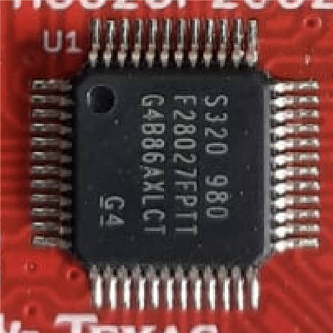
TARGET MCU : TMS320F28027F

REFERENCE DESIGN : LAUNCHXL-F28027F + BOOSTXL-DRV8305EVM

CCS VERSION : 10.3.1

EXAMPLE PROJECT : LAB 05 (b)

---------------------------------------------------------------------------------------------------------------------------------------------------------------------------------------------------

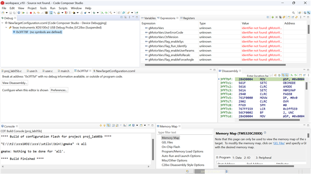
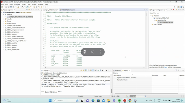
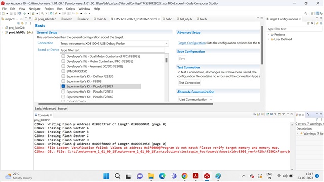
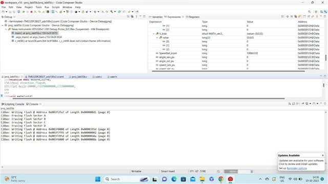
ERROR1 :  0X3FF7BF ( no symbols are defined )

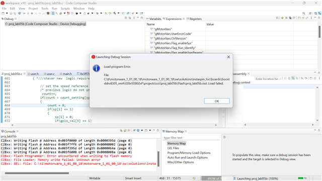
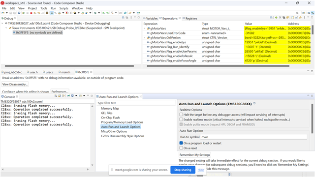
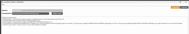
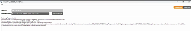
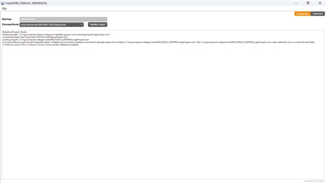
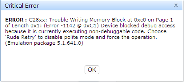
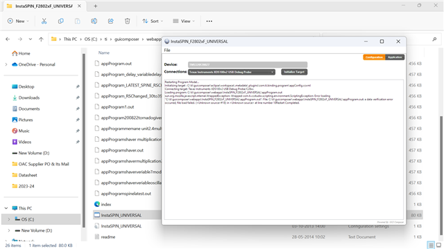
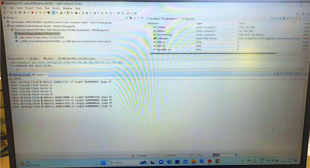
ERROR 2 : Load Program Error

---------------------------------------------------------------------------------------------------------------------------------------------------------------------------------------------------

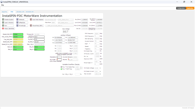
ISSUE : Unable to load the file in custom board to test the functionality

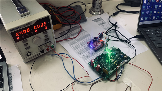
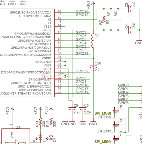
We have designed custom board taking reference from LAUNCHXL-F28027F + BOOSTXL-DRV8305EVM

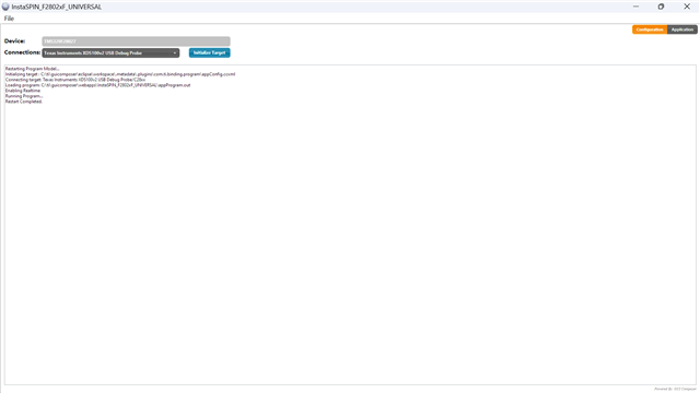
W are using another LAUNCHXL-F28027F ( from which TMS320F28027F is disassembled ) as a debugger ( Image Attached )

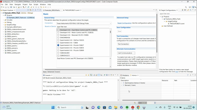
Upon connection of debugger to target hardwware & checking TEST CONNECTION. The debug connection is becoming successful.

Considering debug connection are correct, we are trying to load program given under Lab 05 ( b).

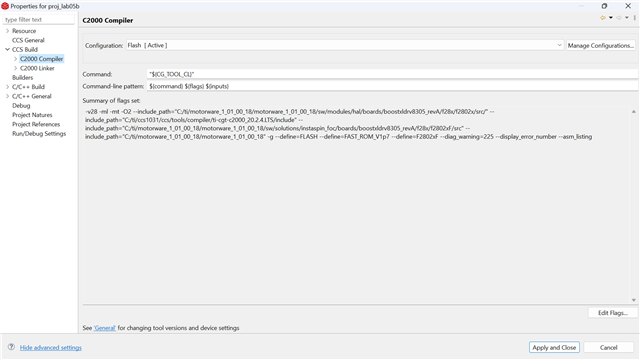
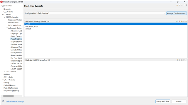
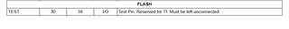
We have ensured the predefined symbols (Project properties > Build > C2000 Compiler > Predefined Symbols) "FLASH", "F2802xF" and "FAST_ROM_V1p7" defined.

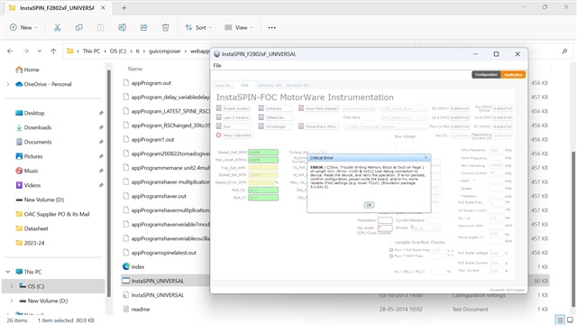
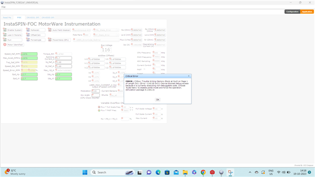
Despite of all above, we get Load Program Error ( Image attached )O

Also we get 0X3FF7BF ( no symbols are defined )

We are absolutely not getting any clue how to resolve this.

Please suggest.

  • If you configure the boot mode to "wait boot" on this device, and re-try the flash program does that fix the issue?  If not please go the below/

    You may want to try to connect to the device, vs the automatic action of the "debug" button, as this will give a better idea of the fail that is happening.

    To do this you want to bring up the "target configuration" window  View->target configurations; then right click on the ccxml file and "Launch ccxml file"  from there you can connect the device and see if you can just erase the flash from the on-chip flash tools.

    If you have not yet created a target config, just right click in the target config window and create one for your device.  It should be pretty straightforward to do so, just have to fill in the debug probe and device type.

    Best,

    Matthew

  • I could able to connect to the device.

    After connection - I could able to erase the flash ( Screenshot attached )

    But after I load the .out file - the situation remains same.

    Every time it should no symbols are define. 

    One more observation is some random values are visible under expression tab. 

    In fact if I try to load the file to target hardware by going into instaspin FOC utility - program gets loaded. But some random values are displayed under various options. 

  • Shivam,

    Since the erase worked correctly, I think the schematic/device power/grounds are likely OK.  Would it be possible to take a picture of the top marking of the C2000 MCU and post it here?  I want to make sure that the part number is matching to the 27F, which has the flash available to program.  If this is another variant of the  2802x family it may have less flash, hence this error.

    Best,

    Matthew

  • Matthew,

    Thank for pointing out unchecked thing.

    The  LAUNCHXL-F28027F is having IC with marking  

    S320  980

    F28027FPTT

    G4B86AXL CT

                     G4

    /resized-image/__size/640x480/__key/communityserver-discussions-components-files/171/Screenshot-2023_2D00_09_2D00_06-at-3.58.26-PM.png

    And the IC we installed on the custom board is having below marking 

    S320  980

    F28027PTO

    CA28CH981

                   C4

    /resized-image/__size/640x480/__key/communityserver-discussions-components-files/171/Screenshot-2023_2D00_09_2D00_06-at-3.59.49-PM.png

    Surely they both don't look same. 

    I believe F28027FPTT is for FOC and F28027PTO is not for FOC. Please confirm this.

    However, we placed the order of TMS320F28027PTQ looking at the BOM & Schematic of eval kit. 

    In the BOM - TMS320F28027PTS was mentioned. against which we placed order for TMS320F28027PTQ as it was having less lead time.

    Anyway - considering the fact that MCU on EVAL kit & on custom board is not same we did A2A Swap. Both ICs are swapped.

    /resized-image/__size/640x480/__key/communityserver-discussions-components-files/171/6354.error_5F00_1.png

    Above error were displayed when we tried loading .out file.

    Also when we tried functional TI eval kit after placing ordered part on it - it was also not able to function as it was functional earlier.

    /resized-image/__size/640x480/__key/communityserver-discussions-components-files/171/Error_5F00_2_5F00_withourIC_5F00_on-TIboard.jpg

    /resized-image/__size/640x480/__key/communityserver-discussions-components-files/171/error_5F00_3_5F00_withourIC_5F00_onTIboard_5F00_randomvalues.jpg

    Above were the errors. And some random values got displayed on InstaSpin UI.

    Please suggest.

  • Shivam,

    You are correct on the difference in the 2 devices; the F28027 does not support INSTASPIN FOC libaries(they are located in the ROM of the 27F device).

    If these were called/referenced then the non "F" device would jump to code that is not on the device.  However, the amount of flash on these devices is identical.

    When you are connecting to the non -F device with CCS, have you changed the ccxml file target to match the F28027(no F) PN?  I think there may be some differences in the part number stored in the OTP that CCS may read before attempting to program.  I'm not sure this will cause the above error, but would be good to look at.

    Back to the InstaSPIN FOC aspect, that will not work on the 28027 device, even if we resolve the flash issue.  Is that OK for your application, or did you need the FOC support? 

    There is no issue with S vs Q substitution from TI perspective in any of the above, just to address that separately.

    Best,

    Matthew

  • Matthew,

    Thanks for confirming.

    So mistakenly we ordered MOQ of MCUs which are not having F associated to them.

    Anyway - to get things work I just removed the MCU from EVAL kit which is having F part.

    And assembled it on custom board.

    And I am getting attached issue.

    What could be issue now?

    I haven't changed anything in functional code which was perfectly working on eval kit. Its just that I am using custom version of EVAL kit.

    error_1.png.pdf

  • Shivam,

    Thanks for the background, this helps me understand what is going on a bit better.  Agree, all things equal that existing F device should work as it worked before.

    I'd like to take the instaSPIN code out of the picture, can you build and load this project from C2000Ware: C:\ti\c2000\C2000Ware_5_00_00_00\device_support\f2802x\examples\structs\flash_f2802x

    This is a very simple/small program built to load into flash.  I just want to see if we can program this or not.

    Best,

    Matthew

  • Matthew,

    As per your suggestion, we tried building the project from C2000Ware.

    As shown in image - build got successful.

    This time before we attempt flashing - we again checked connection. Connections were successful.

    After that we tried loading .out file as per set practice for eval kit.

    Its showing  ''Data verification error. Load failed"

    Then we again checked selected target configuration.

    The default selection was TMS320F28027. 

    Then considering its not meant for TMS320F28027F we tried finding TMS320F28027F target configuration.

    It was not available. Instead there a configuration "Experimenter's Kit - Piccolo F28027"

    But then also same result.  ''Data verification error. Load failed"

    Please suggest.

  • Matthew, 

    I am attaching schematic for the custom board. 

    You may want to see it in case ( if required ) 

    ARTHRO_CARRIER_V1.0.pdf

  • Shivam,

    Thanks for the schematic, I believe I see the issue. 

    On page 3(The C2000 page), the pin "TEST" is connected to VSS.  This pin needs to be floating per the TI datasheet:

    The flash module will put some voltage on this pin during its operation, since it is grounded it will cause a short and the flash programming will fail.

    Please open this connection and confirm the flash can work as before.

    Best,
    Matthew

  • Matthew, 

    Our schematic is inspired from the reference design.

    In reference design too, the TEST pin is grounded as per below.

    d.

    Despite of this, as per your suggestion we disconnected the pin but no success.

    The program is still not getting flashed. The DEBUG connection were successful this time as well.

  • Shivam,

    Sorry for the false lead, and thanks for pointing out the discrepancy with our reference design.  I must be mistaken on the function of this pin for flash operations.  Let me look a bit more at your previous post to see if there is something I am missing.

    Best,

    Matthew

  • Shivam,

    Can you attach you .cmd (linker) file?  I'd like to double check the memory that we are writing to.

    Best,

    Matthew

  • Hi,

    I have attached .CMD file.

    Please review it.

    Thanks,

    Shivam

    F28027f cmd.docx

  • Shivam,

    Please give me an additional day to review and comment.

    Matt

  • Shivam,

    cmd looks good, for flash the only other thought is that there is some voltage droop caused by higher current demands during program time.  Can you monitor the 3.3V voltage rail of the C2000 when you attempt a program to see if you observe a "glitch" or droop before CCS gives this message?  Can you also confirm the max current you can supply the C2000 on your board?

    Best,

    Matthew

  • Matthew, 

    Assuming many possibilities I kept the working board aside. 

    And I took bare PCB on which I assembled only MCU & its associated passives ( forming the minimum circuit diagram for MCU )

    Then I powered the board via lab power supply which can give upto 3AMPS. 

    I used the same JATG connections. Which become successful. 

    But then SAME result. No successful flashing.

    One observation - while we flash the EVK ( Launchpad + Booster combo ) it taken 47mA approx.

    While the newly assembled only MCU specific board taken 23mA & while flashing it drops to 11mA.

    I am not sure whats wrong but some thing is still a mystery.

    Please suggest. We are stuck up since long.

  • Shivam,

    I'm going to send you a private chat request.  If possible I'd like to see if you share your .out file with me(off forum) if I can program it on my setup here.  Just to rule out a file issue of some sort.  You should see that request soon.

    Best,

    Matthew

  • Shivam,

    I sat down and re-reviewed the schematic again with another TI colleague.  A few things of note:

    1)I had not noticed the first time through, but for the power rails; I see you are using DC/DC buck regulators vs the LDOs we use on the LaunchPad.  Looking a bit deeper the PN list for your 5V rail is same as for the 3.3V rail: K7803-500R3.  This is 3.3V buck, if 5V rail really has this, I think it will compromise not only that rail but anything downstream.  I know you had measured 3.3V earlier, so maybe this is just a schematic error.

    2)For the flash experiment, can we decouple the PWRGOOD from the DRV chip to the XRSn pin of the C2000?  I want to make sure that XRSn is stable during flash programming; there should be a PU resistor(the 10k is OK for now), but I don't want the DRV interfearing here

    3)If all the above doesn't yield anything positive, if we could just supply the C2000 3.3V from an off chip power supply(or even from the original LP) that would be a good experiment.

    Not being able to program the flash is almost always related back to issues with the supply and/or issues with XRSn stability, I think we need to keep our focus on that aspect.

    Best,

    Matthew

  • Hi Matthew,

    Considering there is any issue with 3V3 rail - I removed the DC DC used. Removed the SMD ferrite. 

    And directly powered the rail via lab power supply setting up the voltage to 3.3V & 1 AMP current limit. 

    Surprisingly, this time the result is different. And I believe chip is getting flashed. 

    I am attaching screenshot of my PC for your review.  

    /resized-image/__size/640x480/__key/communityserver-discussions-components-files/171/Screenshot-2023_2D00_10_2D00_23-at-3.31.41-PM.png

    But the problem is not resolved yet as the InstaSpin is showing below error

    "Trouble writing memory block. Device blocked debug access. Chose Rude Retry to disable polite mode "

    For detailed error statement - check below screenshot.

    /resized-image/__size/640x480/__key/communityserver-discussions-components-files/171/Screenshot-2023_2D00_10_2D00_19-141858.png

    Please advise your thoughts on both new events. 

  • Shivan,

    Can you just post the text from that error window?  The image isn't scaling well on my PC, so I can't make out the address that caused the issue.

    I do agree that we are now flashing properly.

    Best,

    Matthew

  • Matthew, 

    I have attached the screenshot again.

    Please check & reply.

  • Shivam,

    Sorry, I need the other screenshot, from InstaSPIN GUI.

    Matt

  • Shivam,

    Sorry, I need the other screenshot of the InstaSPIN GUI.  Whatever you did for the upload format is good though.

    Matt

  • Matt,

    Refer below

  • Shivam,

    I know we've had this discussion before, but the InstaSPIN GUI will not work correctly with a non-InstaSPIN device.  I can't recall if you are using a InstaSPIN device from the lauchPAD on your custom PCB or have the non "F" device.  Please confirm which silicon is in use.

    The region of memory that the INSTASpin GUI is reporting is M0 RAM, which is not secure.  The only reason that this error message would happen is if the device itself is operating in a secure region and the JTAG cannot gain access to the core because of it.  I would advise to check the CSM Passwords, to make sure they are all "0xFFFF" and that a device unlock has been done in your code(just by reading these erased locations).

    Best,
    Matthew

  • Matthew,

    We have used the same chip from eval board on which instaspin is working. So the first query is ruled out.

    Regarding the second query - we haven't done any change in setting / configuration etc. We are just trying to run the same project which is successfully evaluated on the eval kit. We aren't sure how to unlock / check CSM passwords. Please highlight or suggest any application note for this.

  • Shivam,

    A read of the memory addresses at 0x3F 7FF8 to 0x3F 7FFF will unlock the device.  As an experiment, with CCS open and connected to the device, you can open a memory window to this region and verify that you see all 0xFFFF in these locations(the act of opening a memory window will do a read as well).

    If you see all 0x0000 instead, it means that there is some non erased value here and the CSM is active.

    If the above shows 0xFFFF, you can insert the read in your application code near the beginning, and device will stay unlocked for that power on cycle.

    Best,

    Matthew