This thread has been locked.

If you have a related question, please click the "Ask a related question" button in the top right corner. The newly created question will be automatically linked to this question.

TMS320F28035: Flashing issue in TMS320F28035. Device locked

Part Number: TMS320F28035

Hello,

I'm facing flashing issue in TMS320F28035 controller.

With independent control board, flashing and basic functionality of ADC and PWM was tested without any issue.

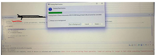
But along with the complete unit, one time we tried debugging without any problem but when tried next time the flashing Is stuck and code was not flashed. From the next time onwards when we try to flash below error is popping up. This happened in both the units we tried to reflash.
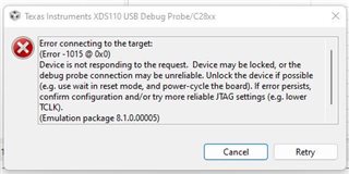
 

Note: We were already using this controller for previous versions and never faced this issue.  In the new version we have only few changes related to GPIO and ADC pins.

          Instead of GPIO12 and GPIO16 we changed it to GPIO6 and GPIO7. ADCINB4 and ADCINB6 pins are used as ADC for temperature monitoring.

Can you help me in understanding what might cause this issue. Is there any way I can unlock the device?

Thanks & regards,

Madhu P

  • Hi,

    Can you try putting the device in wait boot mode? Did you program a password onto the device? 

    Best Regards,

    Ben Collier

  • Hello Mr.Benjamin,

    There was no password written into it. 

    Can you help me on how I can enter boot mode. I'm using XDS110 debugger. Whenever I try to debug, the pop up will come with device locked error.

    Best regards,

    Madhu P

  • Madhu,

    I apologize, there is no wait boot mode on this device. Could you please use the boot select pins to put the device in SCI boot mode? There is a table in the TRM which will describe what you will need to do with the boot select pins.

    Best Regards,

    Ben Collier

  • Hello Mr.Benjamin,

    I'll look for the possibility to use boot pins to boot in SCI mode.

    One more observation: I've tried flashing in one other unit, the flashing started and got stuck in Erasing sector C step for some time and retried 2 to 3 times automatically and stopped with Load Program Error pop-up.

    Is there any log I can store while flashing to send it to you for better analysis?

    Thanks & Regards,

    Madhu P

  • Madhu,

    I will have to ask about that possibility and get back to you tomorrow.

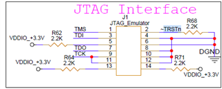
    Also, could you try opening your target configuration and using the 'Test Connection' option? From your previous error, I think that the test will pass, but it will confirm that your JTAG signal layout is ok.

    Best Regards,

    Ben Collier

  • Hi,

    I apologize for the delay getting back to you. I think the best way to share this information would just be to copy and paste the console output.

    Also, I saw that you started another thread for flash support, so please let me know if you want to continue debugging this issue in this thread. 

    Best Regards,

    Ben Collier

  • Hello Mr.Benjamin,

    As the project is in end stage, I need to resolve this issue ASAP. We will keep this thread active and parallelly will try find solution from the TI support team for  our company. We will close this once we find a solution.

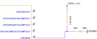
    Regarding SCI boot, it is bit difficult as GPIO34 needs to be set to high as per TRM and we don't have Hw access to make it high. Is there any other possibility to make the unit in WaitBoot mode?

    When I've checked the waveforms, the XRS pin is continuously going low periodically at 14msec even though 3.3V and 1.8V are stable. Will this also be a reason for giving Device may be locked error? 

    Is it okay if I give separate 3.3V supply just to XRS pin and keeping the remaining supplies same?

    Regards,

    Madhu P

  • Hi Madhu,

    It is expected to see the pulses on XRSn on an unprogrammed device due to the watchdog reset. This will not cause the locked error that you are seeing. 

    The only way to change the boot mode without changing GPIOs 34 and 37 would be to program a certain location in the OTP, which is not possible without connecting to the device.

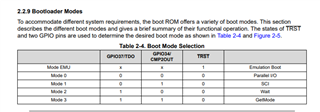
    Also, I was mistaken about this device not having a wait boot mode, here is the boot mode table from the TRM:

    It would be good if you could change any of the GPIOs to avoid booting to FLASH, which will be the case in GetMode.

    Also, I saw in an email from our field team that you were able to successfully flash one of your devices when using an external power supply. Did that solve the issue that you described here?  

    I've tried flashing in one other unit, the flashing started and got stuck in Erasing sector C step for some time and retried 2 to 3 times automatically and stopped with Load Program Error pop-up.

    Best Regards,

    Ben Collier

  • Hello Mr. Benjamin,

    For setting it to SCI boot, issue will be with GPIO34 as we have to hard solder directly on the controller pin and there are chances it might short to the adjacent pins. But anyway we will try as other pins are not used.

    The remaining 2 pins TRST and GPIO37/TDO are directly connected to JTAG interface.

    Once I could able to configure it to SCI boot mode, what are the steps I need to follow to unlock device?

    Regarding your question, I'll explain what happened with the unit while flashing

     - With the complete unit where all the auxiliary supply voltage come from 230V AC supply, when we tried flashing it was stuck in erase sector step and flashing stopped with loading program error. We observed there are some dips in voltages and XRS pin is going low for short duration which was never happened in the previous version units. 

    - Tried by giving +12V external supply and flashing was successful

    - Again tried with 230V and flashing didn't happen. After this try whether it is with 230V or with 12V external supply, flashing process is stopped with below pop up


    As far as now, all the 3units which I retried flashing on 230V supply got locked.

    To debug and to know whether the voltage dip which is happening only during flashing with 230V supply is because of Hardware changes or Software changes, we need to unlock the device and perform experiments. 

    Thanks & regards,

    Madhu P

  • Hi Madhu,

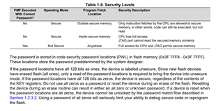
    Please see this screenshot from section 1.2.1 of the Technical Reference Manual:

    If the device is reset during an erase of flash, it is possible to program an unknown password on the device. If there is an unknown password programmed to the device, it will not be possible to unlock the device.

    I suspect that this has happened to your devices that are now locked. When your device boots to flash, the JTAG connection will not be allowed, since the device is running a program from a secured region. If you use one of the other boot modes, the device will wait in boot ROM, and the connection with JTAG can be established. I think this would be useful because you can check the register mentioned in the above TRM section, and you will be able to confirm that your devices are locked and there is not some other issue going on. You will not be able to unlock the devices that have unknown passwords programmed. 

    If you are able to confirm that your devices are locked, then it seems that the root cause of your problem is an unreliable power supply to the F28035 device that is causing the device to be reset during flash erases, which can cause an unknown password to be programmed to the device. I think the focus can now shift to improving the power supplies for the F28035 device.

    Best Regards,

    Ben Collier