
- Ask a related questionWhat is a related question?A related question is a question created from another question. When the related question is created, it will be automatically linked to the original question.
Hello,
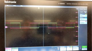
I am trying to write code for my F28379D DSP, but unfortunetly I can not add 180 degree phase shift to my hardware pins even though I have added it in my code. Can anyone please help? Sorry for putting down the code like this below, but the add code option was giving me error when I was adding it there. Please see the code below:
#include <math.h>
#include "PS_bios.h"
#define GetCurTime() PS_GetSysTimer()
#define PWM_IN_CHECK // To lower PWM value setting time, comment out this line if PWM duty cycle values are strictly limited in the range.
interrupt void Task();
interrupt void Task_1();
#ifdef _FLASH
#pragma DATA_SECTION(PSK_SysClk, "copysections")
#endif
const Uint16 PSK_SysClk = 200; // MHz
extern DefaultType fGblSUM25;
extern DefaultType fGblPre_PI;
extern DefaultType fGblI_ref;
extern DefaultType fGblFinj1;
extern DefaultType fGblPost_PI;
// Parameters in parameter file _ParamFile1
#define DC_link 85.0
#define samp 100000.0
#define load 48.0
DefaultType fGblSUM25 = 0;
DefaultType fGblPre_PI = 0;
DefaultType fGblI_ref = 0;
DefaultType fGblFinj1 = 0;
DefaultType fGblPost_PI = 0;
interrupt void Task()
{
DefaultType fS6, fSUM22, fC3, fC14, fVDC6, fCurentGain1, fSUM20, fZOH6;
DefaultType fF2837x_ADC2_2, fZOH5, fF2837x_ADC1_2, fCurrent_Reference;
ADC_CLR(2) = 1<<(1-1);
CPU_PIEACK |= M__INT1;
fCurrent_Reference = 2;
fF2837x_ADC1_2 = ADC_RESULT(2, 0) * (1.0 * 3.3 / 4096.0);
fZOH5 = fF2837x_ADC1_2;
fF2837x_ADC2_2 = ADC_RESULT(1, 0) * (1.0 * 3.3 / 4096.0);
fZOH6 = fF2837x_ADC2_2;
fSUM20 = fZOH5 - fZOH6;
fCurentGain1 = fSUM20 * ((-1)/0.048);
fGblSUM25 = fCurrent_Reference - fCurentGain1;
#ifdef _DEBUG
fGblPre_PI = fGblSUM25;
#endif
#ifdef _DEBUG
fGblI_ref = fCurrent_Reference;
#endif
fVDC6 = 0;
fC14 = 0.58;
fC3 = (-75E-3);
fSUM22 = fCurentGain1 - fC3;
{
static DefaultType fOutVal = 0.0;
const DefaultType b0 = (1.0*1.0)/100.0E3/(1.0/(2*3.14159*50.0)+1.0/100.0E3);
const DefaultType a1 = -1.0/(2*3.14159*50.0)/(1.0/(2*3.14159*50.0)+1.0/100.0E3);
fS6 = b0 * fSUM22 - a1 * fOutVal;
fOutVal = fS6;
}
// Start of changing PWM2(2ph) registers
// End of changing PWM2(2ph) registers
// Start of changing PWM1(2ph) registers
// End of changing PWM1(2ph) registers
// Start of changing PWM3(2ph) registers
// End of changing PWM3(2ph) registers
// Start of changing PWM4(2ph) registers
// End of changing PWM4(2ph) registers
// Start of changing PWM5(1ph) registers
// Set Duty Cycle
{
DefaultType _val = __fsat(fVDC6, 1 + 0, 0);
_val = PWM_TBPRD(5) * (((1 + 0) - _val) * (1.0 / 1));
PWM_CMPA(5) = (int)_val;
}
// End of changing PWM5(1ph) registers
// Start of changing PWM6(1ph) registers
// Set Duty Cycle
{
DefaultType _val = __fsat(fVDC6, 1 + 0, 0);
_val = PWM_TBPRD(6) * (((1 + 0) - _val) * (1.0 / 1));
PWM_CMPA(6) = (int)_val;
}
// End of changing PWM6(1ph) registers
}
interrupt void Task_1()
{
DefaultType fFCNM8, fPIz;
PSM_Timer1IntrEntry();
{ // backward Euler
static DefaultType out_A = 0.0;
fPIz = out_A + ((200.0E-3)/((100.0E-6)*50000L)) * fGblSUM25;
fPIz = (fPIz < 0.5) ? 0.5 : ((fPIz > 2.0) ? 2.0 : fPIz);
out_A = fPIz;
fPIz += (200.0E-3) * fGblSUM25;
fPIz = (fPIz < 0.5) ? 0.5 : ((fPIz > 2.0) ? 2.0 : fPIz);
}
fFCNM8 = 1.0/fPIz;
#ifdef _DEBUG
fGblFinj1 = fFCNM8;
#endif
#ifdef _DEBUG
fGblPost_PI = fFCNM8;
#endif
}
void Initialize(void)
{
PS_SysInit(2, 10);
PS_PwmStartStopClock(0); // Stop Pwm Clock
PS_TimerInit(0, 0);
// Set initial states for those GPIO output ports.
PSM_GpioSetOutput(32, 0); // Reset GPIO32
PS_GpioSetFunc(32, 0, eSync1Samp, eGpioOutPullup, 0); // Initialize GPIO32
PSM_GpioSetOutput(61, 0); // Reset GPIO61
PS_GpioSetFunc(61, 0, eSync1Samp, eGpioOutPullup, 0); // Initialize GPIO61
PSM_GpioSetOutput(95, 0); // Reset GPIO95
PS_GpioSetFunc(95, 0, eSync1Samp, eGpioOutPullup, 0); // Initialize GPIO95
PSM_GpioSetOutput(96, 0); // Reset GPIO96
PS_GpioSetFunc(96, 0, eSync1Samp, eGpioOutPullup, 0); // Initialize GPIO96
PSM_GpioSetOutput(97, 0); // Reset GPIO97
PS_GpioSetFunc(97, 0, eSync1Samp, eGpioOutPullup, 0); // Initialize GPIO97
PSM_GpioSetOutput(104, 0); // Reset GPIO104
PS_GpioSetFunc(104, 0, eSync1Samp, eGpioOutPullup, 0); // Initialize GPIO104
PSM_GpioSetOutput(123, 0); // Reset GPIO123
PS_GpioSetFunc(123, 0, eSync1Samp, eGpioOutPullup, 0); // Initialize GPIO123
{
int i, preAdcNo = -1;
/* PST_AdcAttr: Adc No., Channel No., Soc No., Trig Src, SampleTime(clock) */
const PST_AdcAttr aryAdcInit[2] = {
{2, 2, 0, ADCTRIG_PWM5, 20},
{1, 2, 0, ADCTRIG_PWM5, 20}};
const PST_AdcAttr *p = aryAdcInit;
for (i = 0; i < 2; i++, p++) {
if (preAdcNo != p->nAdcNo) {
PS_AdcInit(p->nAdcNo);
preAdcNo = p->nAdcNo;
}
PS_AdcSetChn(p->nAdcNo, p->nChnNo, p->nSocNo, p->nTrigSrc, p->nWindSz);
}
}
PS_PwmInit(1, 0, 1, 1.e6/(samp*1.0), ePwmUseAB, ePwmTogglePRD, ePwmDoNothingCmp, HRPWM_DISABLE); // pwmNo, pinSel, waveType, period, outtype, PwmA, PWMB, UseHRPwm
PS_PwmSetDeadBand(1, 0, 0, 0, 0, 0, 0);
PS_PwmSetIntrType(1, ePwmNoAdc, 1, 0);
PS_PwmSetNewTripAction(1, 0, eTzHiZ2, eTzHiZ2, eTzHiZ2, eTzHiZ2);
PWM_CMPA(1) = (0 * (1.0 / 1)) * PWM_TBPRD(1);
PWM_CMPB(1) = (0 * (1.0 / 1)) * PWM_TBPRD(1);
PSM_PwmStart(1);
PS_PwmInit(2, 0, 1, 1.e6/(samp*1.0), ePwmUseAB, ePwmResetValleySetPeak, ePwmDoNothingCmp, HRPWM_DISABLE); // pwmNo, pinSel, waveType, period, outtype, PwmA, PWMB, UseHRPwm
PS_PwmSetDeadBand(2, 0, 0, 2, 0, 0, 0);
PS_PwmSetPhaseDelay(2, 1, 180 * (1.0 / 360.0));
PS_PwmSetIntrType(2, ePwmNoAdc, 1, 0);
PS_PwmSetNewTripAction(2, 2, eTzHiZ2, eTzHiZ2, eTzHiZ2, eTzHiZ2);
PWM_CMPA(2) = ((1 - 0) * (1.0 / 1)) * PWM_TBPRD(2);
PSM_PwmStart(2);
PS_PwmInit(3, 0, 1, 1.e6/(samp*1.0), ePwmUseAB, ePwmResetValleySetPeak, ePwmDoNothingCmp, HRPWM_DISABLE); // pwmNo, pinSel, waveType, period, outtype, PwmA, PWMB, UseHRPwm
PS_PwmSetDeadBand(3, 0, 0, 2, 0, 0, 0);
PS_PwmSetPhaseDelay(3, 1, 180 * (1.0 / 360.0));
PS_PwmSetIntrType(3, ePwmNoAdc, 1, 0);
PS_PwmSetNewTripAction(3, 0, eTzHiZ2, eTzHiZ2, eTzHiZ2, eTzHiZ2);
PWM_CMPA(3) = ((1 - 0) * (1.0 / 1)) * PWM_TBPRD(3);
PSM_PwmStart(3);
PS_PwmInit(4, 0, 1, 1.e6/(samp*1.0), ePwmUseAB, ePwmTogglePRD, ePwmDoNothingCmp, HRPWM_DISABLE); // pwmNo, pinSel, waveType, period, outtype, PwmA, PWMB, UseHRPwm
PS_PwmSetDeadBand(4, 0, 0, 0, 0, 0, 0);
PS_PwmSetIntrType(4, ePwmNoAdc, 1, 0);
PS_PwmSetNewTripAction(4, 0, eTzHiZ2, eTzHiZ2, eTzHiZ2, eTzHiZ2);
PWM_CMPA(4) = (0 * (1.0 / 1)) * PWM_TBPRD(4);
PWM_CMPB(4) = (0 * (1.0 / 1)) * PWM_TBPRD(4);
PSM_PwmStart(4);
PS_PwmInit(5, 0, 1, 1.e6/(samp*1.0), ePwmUseAB, ePwmStartLow1, ePwmComplement, HRPWM_DISABLE); // pwmNo, pinSel, waveType, period, outtype, PwmA, PWMB, UseHRPwm
PS_PwmSetDeadBand(5, 0, 2, 3, 0, 0.2, 0.2);
PS_PwmSetPhaseDelay(5, 1, 180 * (1.0 / 360.0));
PS_PwmSetIntrType(5, ePwmIntrAdc, 1, 0);
PS_AdcSetIntr(2, 1, 0, Task); // AdcNo, IntrNo, SocNo, Interrupt Vector
PS_PwmSetTripAction(5, eTzHiZ, eTzHiZ);
PWM_CMPA(5) = (1 + 0 - 0) / (1.0 * 1) * PWM_TBPRD(5);
PSM_PwmStart(5);
PS_PwmInit(6, 0, 1, 1.e6/(samp*1.0), ePwmUseAB, ePwmStartLow1, ePwmComplement, HRPWM_DISABLE); // pwmNo, pinSel, waveType, period, outtype, PwmA, PWMB, UseHRPwm
PS_PwmSetDeadBand(6, 0, 2, 3, 0, 0.2, 0.2);
PS_PwmSetPhaseDelay(6, 1, 180 * (1.0 / 360.0));
PS_PwmSetIntrType(6, ePwmNoAdc, 1, 0);
PS_PwmSetTripAction(6, eTzHiZ, eTzHiZ);
PWM_CMPA(6) = (1 + 0 - 0) / (1.0 * 1) * PWM_TBPRD(6);
PSM_PwmStart(6);
PS_TimerInit(1, 4000L);
PS_TimerSetIntrVector(1, Task_1); // set timer1 interrupt vector
PS_PwmStartStopClock(2); // Start Pwm Clock, start Timer1
}
void main()
{
Initialize();
PSM_EnableIntr(); // Enable Global interrupt INTM
PSM_EnableDbgm();
for (;;) {
}
}


