
- Ask a related questionWhat is a related question?A related question is a question created from another question. When the related question is created, it will be automatically linked to the original question.
Hi Team,
• Background:
during LLC charging process; ePWM3&4 driving LLC H-Bridge; PWM frequency 80k~150k(set by software); resonant operating frequency 90kHz;
The waveform is captured by monitor the C2000 device's ePWM output pins, an isolation is added between MOS driver and C2000:

(The left pins pointed by the red arrow are connected to C2000)
MOS driver:

ePWM configure code:
update ePWM parameters code:
• issue:
When the LLC adjusts the frequency downward from 85K to close to 80K, there is a chance that the drive signals of the upper and lower half-bridge MOS tubes will occasionally be high at the same time.
The MOS tube is short-circuited and the tube is burned out.


The waveform and frequency before shorted:

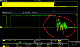
The following figure shows the waveform at the moment of short circuit (PI parameters are not adjusted well), output oscillation occurs: blue is the LLC input voltage, yellow is the LLC resonant inductor current, and green is the LLC output current.

This issue occurs at the every C2000 devices occasionally. The conditions that occur are that during the charging and starting process, the LLC output is loaded for a few seconds, the LLC input voltage drops, and then the LLC performs frequency modulation. The frequency is close to the lower limit frequency of about 80K, and a through short circuit may occur.
The customer generate Dead-Band time by using different compare value with different action. The DB module is bypassed.
The glitches on ePWM output pins make me confused:
--
Thanks & Regards


