- Ask a related questionWhat is a related question?A related question is a question created from another question. When the related question is created, it will be automatically linked to the original question.

Hello:
I encountered such a problem when configuring HRPWM with the TMS320F28335 series chip. The configuration code is as follows:
void
HRPWM6_Config(period)
{
//
// ePWM6 register configuration with HRPWM
// ePWM6A toggle high/low with MEP control on falling edge
//
EPwm6Regs.TBCTL.bit.PRDLD = TB_IMMEDIATE; // set Immediate load
EPwm6Regs.TBPRD = period-1;
EPwm6Regs.CMPA.half.CMPA = 0;// set duty control only by CMPAHR
EPwm6Regs.CMPA.half.CMPAHR = (255<< 8); // initialize HRPWM extension
EPwm6Regs.TBPHS.all = 0;
EPwm6Regs.TBCTR = 0;
EPwm6Regs.TBCTL.bit.CTRMODE = TB_COUNT_DOWN;//count down mode
EPwm6Regs.TBCTL.bit.PHSEN = TB_DISABLE; // ePWM6 is the Master
EPwm6Regs.TBCTL.bit.SYNCOSEL = TB_SYNC_DISABLE;
EPwm6Regs.TBCTL.bit.HSPCLKDIV = TB_DIV1;
EPwm6Regs.TBCTL.bit.CLKDIV = TB_DIV1;
EPwm6Regs.CMPCTL.bit.LOADAMODE = CC_CTR_ZERO;
EPwm6Regs.CMPCTL.bit.LOADBMODE = CC_CTR_ZERO;
EPwm6Regs.CMPCTL.bit.SHDWAMODE = CC_SHADOW;
EPwm6Regs.CMPCTL.bit.SHDWBMODE = CC_SHADOW;
EPwm6Regs.AQCTLA.bit.ZRO = AQ_CLEAR; // PWM toggle high/low
EPwm6Regs.AQCTLA.bit.CAD = AQ_SET;
//EPwm6Regs.AQCTLB.bit.PRD = AQ_CLEAR;
//EPwm6Regs.AQCTLB.bit.CBU = AQ_CLEAR;
EALLOW;
EPwm6Regs.HRCNFG.all = 0x0;
EPwm6Regs.HRCNFG.bit.EDGMODE = HR_REP; // MEP control on raising edge
EPwm6Regs.HRCNFG.bit.CTLMODE = HR_CMP;
EPwm6Regs.HRCNFG.bit.HRLOAD = HR_CTR_ZERO;
EDIS;
}
In the main function, I configure SYSCLKOUT=150MHz and TBCLK=150MHz, and pass 15 as the period parameter into the HRPWM6_Config(period) function, so the generated PWM frequency is 15MHz. Now I just want to control the duty cycle with CMPAHR, so configure CMPA to 0, while CMPAHR=255, when CTR = CAD, the output is set, and when CTR = ZRO, the output is clear, MEP of TMS320F28335 =150ps, so the pulse width of the generated PWM should be 255x150ps = 38.25, but I can't see such PWM output on the oscilloscope. I would like to ask if it is possible to control the duty cycle of PWM by using CMPAHR only. In other words, can CMPA be configured to 0 in high-precision mode
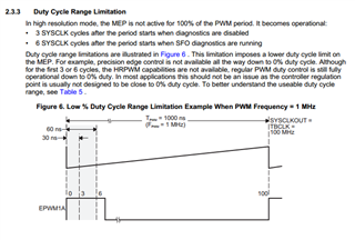
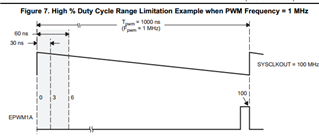
At the same time, in order to avoid the limitation in HRPWM mode, the count mode is configured as COUNT_DOWN, and MEP is used to control the output rising edge REP, as shown in the following figure:
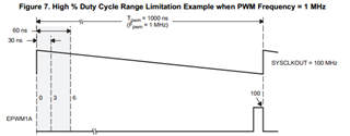
According to this document, it is possible to achieve high-precision PWM output by configuring the rising edge REP with MEP when the count is approaching 0, so I wonder if it is possible to configure CMPA to 0, in other words, when CMPA=0, is the MEP technology of HRPWM mode still available?
If I want to see an MEP edge, how much bandwidth do I need to use the oscilloscope? Moreover, I found during the configuration that when the PWM output is 30MHz 50% duty cycle, the PWM waveform output from GPIO is close to the sine wave after oscilloscope sampling (the oscilloscope bandwidth is 200MHz), and when the PWM frequency is reduced to 15MHz, the waveform is relatively distorted, as shown in the following figure: