Other Parts Discussed in Thread: C2000WARE
Hello,
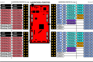
I have designed an MPC controller in Simulink, I want to provide two analog input signals one from the plant and another reference signal to MPC, and send the generated control output to my plant. I purchased TI LAUNCHXL-F28379D, but I am not sure which pins correspond to real-time operations. Looking at the device technical manual I think the Analog Out pin will be connected to MV of the controller and DAC1 and DAC2 will be input to the controller from the real device. But I am not sure if these pins are for real-time or not because I read somewhere that PMW pins correspond to real-time operations.
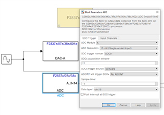
If I am right then for DAC there is nothing complex I just need to connect the wires and select ports among A, B, and C. But when it comes to ADC block there are a lot of options to keep them default or change, I am not sure what these mean, even I read the Matlab Help section but I am unable to understand them.
I am seeking help in this regard, the real device output signal is Analog DC Voltage which contains a 2-5 Hz frequency signal (topography) of my sample. Please suggest me ADc block settings based on my Analog Input signal.