This thread has been locked.

If you have a related question, please click the "Ask a related question" button in the top right corner. The newly created question will be automatically linked to this question.

TMS320F2812: Losing internal flash and passwords disappear after an indeterminant amount of time

Part Number: TMS320F2812
Other Parts Discussed in Thread: UNIFLASH

We have used the TMSF2812 for over 15 years and have more than 20 different applications that are based on the 2812.  Starting approximately 2 years ago, we have started seeing a problem where on some boards, but not all, systems will lock up.  Investigating on a test setup, I can see through JTAG that an illegal ISR is triggered and when that occurs, I can see internal flash reports all 0 and the security passwords show 0.  Before the lockup, the security passwords are correct.  It appears that they are not really gone.  Simply resetting the firmware through JTAG, the passwords are back.  The time that it takes to lockup varies quite a bit.  Heating the board makes it more likely to occur.  Again, this problem has appeared across multiple applications.  But we also see that using one application on multiple boards shows that the problem only occurs on a subset of those boards.  We have been unable to isolate this problem to hardware or software so far, although hardware seems likely.

I would appreciate any suggestions on what we should look at based on these observations.

Thank you very much!

  • Hello Sandy,

    Heating the board makes it more likely to occur.

    Can you clarify on this point, does the error occur regardless of temperature? Is there a certain temperature at which the observed error will definitely occur, or is it just at higher temperatures the issue will be more likely to occur (but not impossible at low/room temperature)?

  • The error can occur at any temperature, it is just that at a higher temperature it can shorten the time that it takes to occur. 

    One other observation that I can make is that when the illegal ISR occurs, one can see the previous execution in the Debug window.  More often than not, the previous execution listed is args_main.c and the illegal ISR occurs when the function attempts to return.  As far as I know, that function should only be called at startup and there is no indication of any reset when monitoring the reset line with a scope.

    Thank you very much!

  • Hi Sandy,

    Just some follow up questions:

    1. You stated that the issue was observed about 2 years ago, was there any change in hardware or software near this point in time?
    2. If you try to run the application in RAM, is there any difference?
    3. Are the Flash wait states configured per the datasheet? (See Table 8-5. Minimum Required Flash Wait States at Different Frequencies in the datasheet)
  • Hi Omer,

    In answer to your questions,

    1.  This issue shows up across multiple firmwares,  many of them have NOT been  changed in that timeframe.  Hardware wise, the TI chip has been upgraded and we changed the manufacturer of external flash which is only used in one of the projects.

    2. I very much doubt that I can fit the application into just RAM

    3. The Flash wait states are set to 5 which I verified in JTAG.  When the device locks up, the values then show up as 0.

    Thank you very much!

  • Hardware wise, the TI chip has been upgraded

    Sorry, can you clarify this point? Were you not using a F2812 device up to this point or did you change from this device?

  • Hi Omer,

    Always been a  F2812 processor, just a later date code

    Thanks!

    Sandy

  • Hello Sandy,

    I will check with another expert and get back to you.

  • Hi Omer,

    An additional question, in the meantime.

    How we can identify if a processor is in boundary scan mode?  We have EMU0 and EMU1 pulled up with a 2.2k resistor.  TRST is pulled down with a 1k resistor.  Tapping the EMU1 pin to ground through a 1k resistor will "lockup processor" but does not appear to cause an illegal ISR.

  • Hello Sandy,

    It would be better to create a separate post for threads on a different topic, otherwise it will be difficult trying to coordinate with other experts to respond on this thread.

  • Hello Omer,

    This question is an inquiry based on our troubleshooting of this problem.  I stated that it did not cause an illegal ISR, but through further investigation we found that it does sometimes cause an illegal ISR.  Both that scenario and the lockup problem always lockup but the illegal ISR (we are now monitoring through a digital output) sometimes occurs, but not always.

    Thank you!

  • Hello Sandy,

    Currently both our JTAG experts are out-of-office, so I'll reach out to them tomorrow and see if I can get them to answer your question.

  • Sandy,

                You mention you observed this issue 2 years ago. What was the resolution? Was your problem resolved after replacing the chip? Also, what is the DPPM number for this issue?

  • Hareesh,

    When this issue first started two years ago, we were suspicious of the 2812 processor, date codes 1A and 94.  It appeared that if we replaced the 2812 processor, the problem went away, or so we thought.  Eventually, as our product was distributed to customers, we came to realize that the problem was still there.

    In response to your other question concerning the DPPM, I am not sure what DPPM stands for.  If it means a case number or forum issue #, this is the first issue that we have opened.

    Thank you for your help!

    Sandy

  • Hello Sandy,

    DPPM refers to Defective Parts Per Million.

  • Hareesh and Omer,

    We have purchased a total of 840 MA2325-3 between 2018 and end of 2022 and we can confirm the total failure is 45 products that we have seen this happing with (5.357%).

    Additionally, about half of the PCB’s have been returned due to suspicious behavior.  Further investigation may reveal different failure rate numbers.  We can say with certainty that the volume of returns for 2812 products has drastically increased in the last couple of years.

    Testing confirmed failure boards, we have observed the following:

    1. We have been unable so far to associate this lockup with any particular section of code. 

    2. We have removed the security codes and that did not help. 

    3. We see an illegal ISR sometimes, other times the DSP simply locks up and looking at the CPU registers and in debug, the processor appears to be in reset. 

    4. The watchdog has been disabled as part of our testing.

    The bulk of our products are based on the 2812 processor, and we have had to stop shipment of all those products.

    Thank you again for your help!

    Sandy

  • Hello Sandy,

    Can you verify the program time of the device when programming Flash? Also, can you monitor the supply during the program time? What sort of programmer are you using?

  • Omer,

    I am not sure that I understand what you are asking for in the first question?  The programmer is a Blackhawk USB560 emulator.  We have monitored the supply and see no issues.  Can you please explain the first question.

    Thank you very much!

    Sandy

  • Hello Sandy,

    When you program Flash, it takes a certain amount of time. This is outlined in the Specifications section of the datasheet for Flash:

    Also, can you please attach a screenshot of your scope for the supplies? This information will be provided to the quality experts to help make any suggestions.

  • Sandy,

        It is very important the device is not "current-starved" during programming. This means that the power-supply should have sufficent margin (and transient response) to meet the instantanneous and steady-state needs of the device. In addition to meeting the power requirements, you also need to ensure that erase/program timing requirements are being adhered to. Generally, this is taken care of if you are using UniFlash or CCS Flash programmer, since these tools use the Flash programming API 'as is'. Current-starving the device or not meeting the timing requirements could potentially result in "weak-programming" leading to unreliable operation. Having said that, it does intrigue me that resetting the device through CCS makes the problem go away.

  • Hi Sandy, our quality team confirmed that we have shipped millions of F2812 devices in the time frame you mentioned and have not had other customers reporting issues like this so we do not believe there is a systemic quality with the F2812 material. I realize that does not solve your issue and we will continue to brainstorm how to help you debug this, but I wanted to provide some assurance we are not dealing with a silicon quality problem.

    From your testing points above, #3 states that sometimes the device appears to be in reset.  Was that also confirmed by examining XRSN?  Was that repeated for the case you describe in point #4 when the WD was disabled?  I presume you do not have an external supervisor controlling XRSN?

    Do you have a setup in which you can repeatedly and reliably reproduce a failure?  If so, is it possible to take the suspect device and swap it with a device on a known good PCB to see if the failure follows the device or stays with the board?

    By the way, are you operating at 150Mhz/1.9V or 135MHz/1.8V?

    Just thinking 'out loud' here about some root causes we have seen that resulted in intermittent, apparently indiscriminate issues:

    • uninitialized RAM
    • voltage on analog or digital pins before the device is fully powered and/or not adhering to the Power Supply Sequencing section of the datasheet
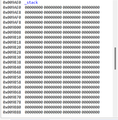
  • We have made a little progress by improving interrupt timing.  Currently the Illegal ISR appears to have stopped, but the processor still halts.  The Blackhawk XDS560v2-USB simply says suspended.  0x0000000 (no symbols are defined).  The stack shows as all 0 and the PC register (core) is 0x0000000.  I am still able to reset the processor and run again.  Any insight on how to troubleshoot this or what state the drive is in when this happens?

    Thank you!

    Sandy

  • Hello Sandy,

    I will check with a JTAG expert to see if they are familiar with this sort of behavior on the device. Are there any error messages that appear in the console? If you look at the disassembly, can you see where the program is if it's pointing to anywhere? I believe 0x0 is where the program starts before jumping to boot ROM.

  • Omer,

    Here are some screen shots to help answer your questions:

    The address is this case is 0x3FFC02, sometimes it is 0x000000.

    Sandy

  • Hello Sandy,

    The JTAG expert stated that this is likely not a problem with the debug probe.

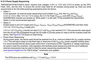
    Based on your Disassembly window, it looks like your device reset. Newer devices have a RESC register to help determine the reset cause, but for this device you will need to do some manual checking. Can you please check the status of the XRS pin when the debugger halts? Also, please verify that the power for the device is sequenced correctly according to the datasheet (see section 8.12.2 Power Supply Sequencing for more information):

  • Omer,

    We have checked the XRS pin multiple times because yes it looks like a reset, but the XRS pin has NOT been triggered.  The XRS pin is high both when the drive is operating correctly and when it trips (it is low active).  Also, the power supply sequencing is correct.  We are using the TPS76D301 power management chip in the same configuration since 2002.  This chip handles all proper power up power supply sequencing.  Also, the watchdog is disabled.

    Sandy

  • Omer,

    Interesting results from our testing last night.  On one of our problem boards, we changed the PLL from 150MHz to 120MHz and the lockup problem disappeared.  We adjusted peripheral clock timings accordingly.  Obviously this is a major change and we are still evaluating.  In the meantime, we are now trying 135MHz and so far no lockup.

    Is there a benchmark test that we could perform to verify the operation at 150MHz?

    Sandy

  • By the way, are you operating at 150Mhz/1.9V or 135MHz/1.8V?

    Sandy what is your core voltage?  150MHz is only supported with 1.9V core.

  • Joe,

    The device supply  voltage is 1.9V

    Sandy

  • Sandy,

                A few points to ponder: 

    1. When you are unable to see the Flash contents, are you able to see L0/L1 RAM contents? If you are not, the device is being inadvertently secured. If you are, we are dealing with something else (perhaps a problem local to Flash)
    2. Does reprogramming Flash make the problem go away?
    3. What method are you using to program the Flash? If you are using our API in a custom programming setup, have you ensured that you use the most recent version of the API?
    4. Can you share the schematics with us privately? Once you accept my friendship request, you will be able to send private messages to me.
    5. Is the issue reproduceable at-will?
    6. If you program a simple GPIO-toggling code in the Flash, do you still see the issue?
    7. Did you measure VDD as close to device as possible? Do you have any current-sensing resistor on Vdd?
  • Hareesh,

    We will attempt to answer your questions, but first I want to let you know that we changed the PLL from 150MHz to 135MHz.  We adjusted peripheral clock timings accordingly.  This was done on two boards and they ran all weekend with no lockup.  Considering the normal time it takes to lockup this is very significant.  Is there a benchmark test that we could perform to verify the operation at 150MHz?

    1.  At this point, we are working with a non-secure chip and we have no issues seeing memory sections.

    2. No it does not.

    3. We are programming using JTAG (Blackhawk USB560 v2 System Trace) with code composer (Version: 11.2.0.00007)

    4. We can share excerpts from the schematic.  I accepted your friend request.  Are there specific areas that you would like to see?

    5. Problem is reproducible on a subset of boards as explained earlier.  On the subset of boards, it is reproducible, but the time frame it takes for the lockup to occur varies.

    6.  We have experimented with Flash today based on your question.  We returned the PLL back to 150MHz.  This project is large enough that there is no way to avoid all execution from Flash, however we were able to move some functions to RAM and even though the lockup problem is still there it did appear to take a longer time to occur.  We have been using the TI defaults of 5 cycles for RANDWAIT and PAGEWAIT.  We have experimented with values of 9 for both RANDWAIT and PAGEWAIT.   The value of 9 is about a 60% increase in execution time for a function executing from Flash.  Then we tried 15 for both RANDWAIT and PAGEWAIT.  This is now a 157% increase in execution time for a function executing from Flash.  In both cases, the drive still locked up.

    7. We measured Vdd as 1.896V very close to the device.  There is no current-sensing resistor on Vdd.

    Thank you for your help!

    Sandy

  • ...

    The device is rated for 150MHz and you should have no issues running it at that speed, provide you (i) feed 1.9v to Vdd (ii) Flash wait-states are configured correctly (iii) Heat generated in the device is conducted away and that the device is not allowed to overheat. (iv) the device is adequately protected from EMI so that it doesn't attempt to execute garbage, triggering an ITRAP.

    Is there a benchmark test that we could perform to verify the operation at 150MHz?

    The device was designed/tested at 150MHz. Moreover, this device is 22+ years old and we have shipped tens of millions of this device. We have not heard of a problem like this.

    1.  At this point, we are working with a non-secure chip and we have no issues seeing memory sections.

    I am afraid you didn't understand the question. Even if you don't have passwords, the device can appear secure if a read of the password locations return anything other than 0xFFFF.

    4. We can share excerpts from the schematic.  I accepted your friend request.  Are there specific areas that you would like to see?

    If you cannot share the whole schematics, I would like to see connections to all the pins of the device.

    5. Problem is reproducible on a subset of boards as explained earlier.  On the subset of boards, it is reproducible, but the time frame it takes for the lockup to occur varies.

    OK, some boards exhibit the problem, some don't. It is unlikely this is a S/W issue. It is H/W but the problem is likely external to our device.

    Then we tried 15 for both RANDWAIT and PAGEWAIT.

    So, the issue is independent of the wait-states used. Even if you use the maximum wait-states, you still see the issue.

    7. We measured Vdd as 1.896V very close to the device.  There is no current-sensing resistor on Vdd.

    OK.

    we found that it does sometimes cause an illegal ISR. 

    When you say an “illegal ISR”, are you referring to an ITRAP?

    The XRS pin is high both when the drive is operating correctly and when it trips (it is low active).

    Depending on how much capacitance is there on the -XRS pin, a WD-initiated reset may not be seen on the -XRS pin.

    3. The Flash wait states are set to 5 which I verified in JTAG.  When the device locks up, the values then show up as 0.

    That is strange. The reset value for the wait-state bits are all 1’s.

    I am concerned we are not converging on a solution even though we have been working on this for the past 25 days. Please see if you can glean anything from the two posts below: 

    https://e2e.ti.com/support/microcontrollers/c2000-microcontrollers-group/c2000/f/c2000-microcontrollers-forum/745014/tms320f2812-bootloader-and-mcu-losing-application-program

    https://e2e.ti.com/support/microcontrollers/c2000-microcontrollers-group/c2000/f/c2000-microcontrollers-forum/743190/tms320f2812-bootloader-and-mcu-losing-application-program

  • A couple of days ago, Joe suggested mounting a “bad” part on a good board and vice versa. Were you able to try this? We need to ascertain if the issue stays with the board or follows the device.

  • Hareesh,

    We had two sets of bad boards and two good boards.  We swapped the chips between the bad boards and the good boards.  In one case the problem followed the chip in the other case it did not.

    And just to clarify, when the drive locks up, I do NOT have to download; all I have to do is reset the processor in order to run again.  It does not appear that any code is lost from Flash.

    We have a very long history, from 2005, that we have been shipping this processor with a variety of firmware, many of which have not been modified in many years.  Starting around 2020, we started to see this problem across many firmware but all using the 2812 platform.

    We continue to look at interaction between the 2812 and the rest of the board, but other than the PLL change to 135MHz, we have been unable to figure out a solution and or cause of the problem.

    Sandy

  • We had two sets of bad boards and two good boards.  We swapped the chips between the bad boards and the good boards.  In one case the problem followed the chip in the other case it did not.

    That doesn't help with our debug Slight frown

    We continue to look at interaction between the 2812 and the rest of the board, but other than the PLL change to 135MHz, we have been unable to figure out a solution and or cause of the problem.

    I think we are reaching a point where we have pretty much exhausted all debug avenues. Do send me the schematics and we can see if something pops out. If not, as a last resort, you can ship a few devices to us for analysis. If that doesn't show any issues for 150 MHz operation, I don't know what else we can do.

  • Hareesh,

    I accepted your friendship request.  We are ready to send you the schematic, if you could let me know how to email.

    Sandy

  • I have already sent you a private message. You could simply reply to my message. You can drag and drop your schematics into the message area. 

    Alternate approach: Just hover the cursor over my name. Below window will pop up. Choose "Send Private Message" option.

  • I reviewed your schematics. Nothing really stood out as an issue. 

    X1/XCLKIN pin is 1.9v level but I see that you have used a series resistor of 20K. I presume you measured the amplitude of the clock signal at X1 pin and that it does not exceed 1.9v. 

    There is a note about power-down sequencing in the datasheet. Hope you are meeting this requirement:

    During power-down, the device reset should be asserted low (8 μs, minimum) before the VDD supply reaches
    1.5 V. This will help to keep on-chip flash logic in reset prior to the VDDIO/VDD power supplies ramping down.
    It is recommended that the device reset control from “Low-Dropout (LDO)” regulators or voltage supervisors
    be used to meet this constraint. LDO regulators that facilitate power-sequencing (with the aid of additional
    external components) may be used to meet the power sequencing requirement

  • Hareesh,

    Thank you for reviewing the schematic.

    Tapping EMU1 pin through a 1.8k resistor to ground will stop CPU operation.  We found this out through previous testing and were hoping that you could maybe offer up an explanation.  All other JTAG signals are treated according to the specification.  We would like to know the mechanism of this event.

    Thank you!

    Sandy

  • EMU0/EMU1 pins are used during JTAG debug and to put the device into boundary scan mode. However, all this is applicable only when the -TRST pin is driven high, which only happens the CCS debugger has control of the device. I am unable to determine exactly what state the device is in when you connect EMU1 pin to GND. That would be an extremely noisy event, which might put the device into some indeterminate state.

    Please comment on the power-down sequencing. Can you capture 1.9v, 3.3v and -XRS during powerdown to check if you are meeting the datasheet requirements?

  • Hareesh,

    We are using the TPS76D301 power management chip in the same configuration since 2002.  This chip handles all proper power up/down sequencing. 

    purple is 3.3V

    blue is 1.9V

    yellow is XRS

    Thank you for your help!

    Sandy

  • It is evident -XRS goes low several milliseconds before VDD even starts ramping down. I am afraid we have exhausted all debug avenues. You can send a few failing units to us for analysis. That would be the last debug option we could pursue.

  • Sandy,

         I will close this post. If you are sending any devices for failure analysis (FA), that communication can be handled through private messages.