


Part Number: TMS320F28379D
Other Parts Discussed in Thread: C2000WARE, , TMDSDOCK28379D, UNIFLASH
Hello everyone,
We have a problem about SCI bootloader located in ti\C2000Ware_5_00_00_00\utilities\flash_programmers directory. We are using SCIA GPIO 84, 85 for updating code via USB-ttl.
Also, our board is TI C2000 TMS320F28379D based TMDSDOCK28379D Experimenter's Kit.
TMS320F28379D: https://www.ti.com/product/TMS320F28379D
TMDSDOCK28379D: https://www.ti.com/tool/TMDSCNCD28379D
First of all, we configured related switch that is:
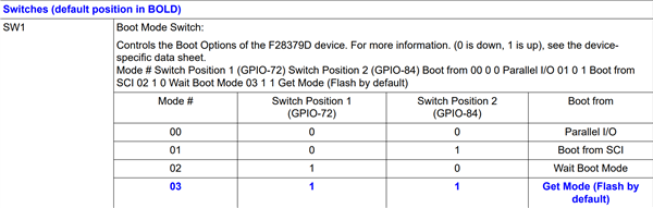
for boot from SCI after that reset the board.
Runing this command on terminal (CMD): serial_flash_programmer.exe -d f2837xD -k F2837xD_sci_flash_kernels_cpu01.txt -a blinky_dc_cpu01.txt -b 76800 -p COM7 located in C:\ti\C2000Ware_5_00_00_00\utilities\flash_programmers\serial_flash_programmer directory. This command executed successfully but it took 5 minutes for flashing Kernel + Application code in this baudrate.
We are trying to increase baudrate but serial_flash_programmer executable didn't work, it stuck in loopback state but not print anything.
What is the problem here? We are using USB-ttl modules that support 1000000 baud for communication.
Also we are tring to port SCIA default pinout GPIO 84, 85 to GPIO 28, 29 for our custom board. We saw this GPIO Assignments in referance manual:
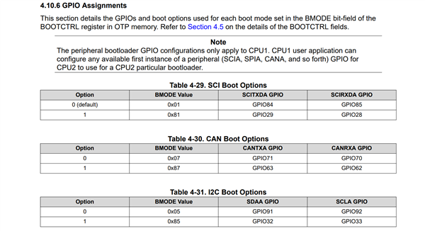
We can change the default GPIOs for bootloader in MCU via this BMODE register. How can we implement this topic in practical case. If I am not mistaken, we can change this register in debug mode, how this work done? This lower speed SCIA problem, also we want to change the boot peripheral that is SCI. How can we change default bootloader peripheral SCI to USB peripheral?
We saw that in referance manual on Emulation Boot Flow Diagrams:

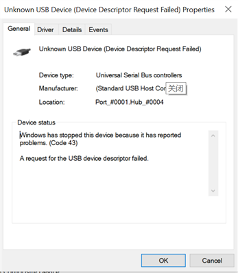
If I am not mistaken, this block diagram is showing us, related registers to succeed this operation. What I understand, we can connect to target board via JTAG and in debug mode. We must change EMU_BMODE value to 0x0C, EMU_KEY 0x5A and CPU reset via CCS debug environment, and run again application in debug mode and process done. Connect TMDSDOCK28379D Experimenter's Kit’s USB peripheral to Host PC and we should see device name in Device Manager that related USB name. Is this work flow correct? We are doing all this steps and we have installed all USB drivers via C200 ware (Windows Device Manager) but we are not seeing related USB port info in Device Manager. (Unknown USB Device or Hidden Device).
Last question about this boot mode selection for OTP. We find this block in referance manual;

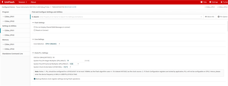
If Emulation boot flow SCI to USB changes works, we must add related value 0x0C5A to Zx-BOOTCTRL registers to brun (permanently). But how can we realise this topic? Can we use UNIFLASH for this purpose or we must change this register on debug mode?
Thanks for everything!
Best Regards,
Furkan S.

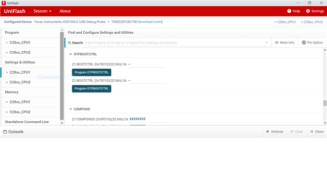
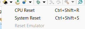
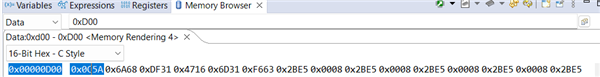
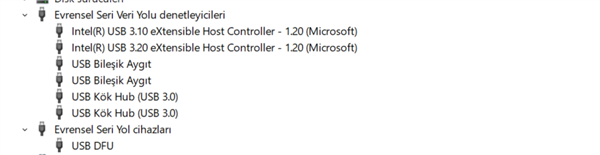
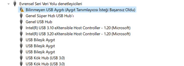 Fig-4. Unknown USB Device in Device Manager