


Other Parts Discussed in Thread: TLV2772
Hello experts,
We are measuring the motor currents using the internal SAR ADC in 12 bit , single ended configuration, and i am having some issues at high speed ranges(20Krpm),
I think it is mostly linked to the current measurement setup that we are using. Could you please clear some doubts on selecting the correct RC values and S+H time.
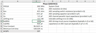
At the moment, in the code the sample window time is 70 ns(ACQPS is 14) ., (14 * 5ns), 200 MHz is the SYSCLK
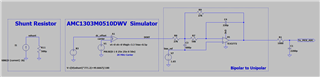
This is how the current is being measured: The drop across a 500 uOhm shunt is measured by a Sigma-Delta ADC(AMC1303M0510DWV) and the Pulses are filtered using a second order lowpass filter using a TLV2772 and then at the MCU's pin we have a RC filter to remove any track high frequency noise picked up.
Looking at the TRM manual section 11.13.2, the equations for calculating the total S+H time is given
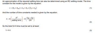
Going by the TRM equations the sample and hold time that i get is 8.8 microseconds which is huge!
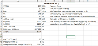
I am planning to reduce the RC values to 200 ohm and 430 pF which gives be a S+H time of about 540 ns, which looks reasonable...
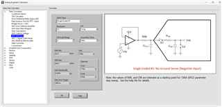
Also referring to the document spract6a (https://www.ti.com/lit/an/spract6a/spract6a.pdf) , in section 2.2 , a tool to calculate the RC filter values is also mentioned!
Going by the Analog Engineer's Calculator tool, The RC value comes out to be 80.5 ohm and 300pF
Which is the more accurate one? i see some deviation from the TRM and the tool?
Also the tool mentions the bandwidth to be 6.28MHz, now in my case I have a delta sigma adc and and opamp together, So should the filter opamp bandwidth be 6.28 MHz or the delta sigma ADC;s BW be 6.28 MHz?
Also wouldn't the RC value be dependent on the incoming input signals frequency ? In my case the maximum speed of the motor would be around 20000 RPM which would produce a sine wave of about 666Hz electrical frequency (round to 1 KHz) , so taking 10x the maximum frequency any opamp with a BW > 10KHz would do?
