This thread has been locked.
If you have a related question, please click the "Ask a related question" button in the top right corner. The newly created question will be automatically linked to this question.
Hello,
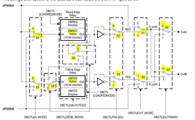
I am trying to use the PWM deadband configuration for one of my application. I have PWM low signal that has been derived from the PWM high signal and it is coplementary. I have the below picture that explains the deadband module configuration in my application. Highlighted switches and the configurations has been ebabled.
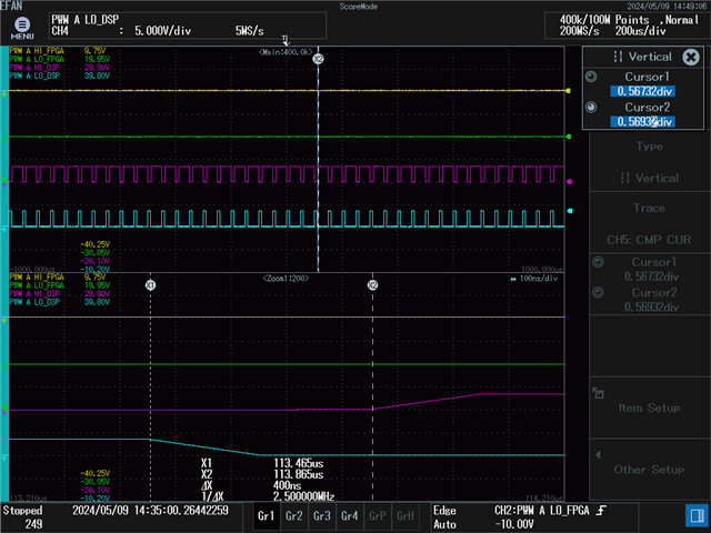
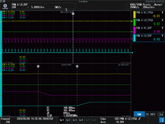
I have the PWM clock (TBCLK) configured for 200MHz and DBRED and DBFED programed for 100 to get the dead band time of 500 nano sec. I expect to see Raising edge will have 500nsec deadtime and Falling edge also will have 500nsec deadtime. However, i witnessed, raising edge is having 400nsec dead time and falling edge is having 600nsec deadtime.
Repeated the same excersite with 300nano sec dead time on both raising and falling edge. Witnessed that, Raising Edge is having 200nsec deadtime and falling edge havinf 400nsec deadtime.
Why the PWM deadtime is not equal on both the edges (Falling and Raising)?
Please help.
Thanks,
Munaf
Hi Munaf,
Rising edge should be equal to falling edge correct. Assuming that measurement from scope is accurate we can see what the issue is in your case
To confirm did you generate same pulse on second channel and compare the edge time difference for delay measurements ?
Also what counter mode is used here ?
Can you also try high resolution DBRED DBFED and see what difference that makes
Thanks
Hi Prarthan,
Thank you for replaying to my query.
At the moment i have only one channel of PWM used.
I have Up-down counter mode enabled in my configuration and not using the high resolution PWM configuration.
Here i am attaching the scope recordings to confirm the inconsistency of the deadband time. Please note, deadtime configured is 500nsec on raising and falling edge. Ignore first two channels in scope recording.
Rasing Edge Scope recording: Where noticed 400nsec deadtime. Expected 500nsec.
Falling Edge Scope recording: Where noticed 600nsec deadtime. Expected 500nsec.
Please do needful.
Thanks,
Munaf
Hi Munaf,
The time should be measured from logic level 1 of falling signal to logic level 1 of rising signal. If you see that would align to 500nsec on both sides.
The rising and falling time of signal can vary depending on the load connected to pin/scope accuracy etc.
Also it seems like your rising and falling time of gpio accounts for 100nsec, that doesnt look right ?
Hi Prarthan,
We might see both the swtiches turn on for little bit time, if considered time from Logic level 1 of falling signal to logic level 1 of raising signal. Typically, this is not advisable daedband measurement, as it lead to shorting the circuit.
Raising and Falling time showed in the scope recordings in the previous my reply is 200nsec. This was monitored in the DSP evaluation kit with docking station. Please advise why this is happening on F28388D Eval kit? Does this mean the Eval board has load that causing the raising and falling time 200nsec?
I have observation below in today's testing. Please note that, all the time i am using the F28388D eval kid that comes with docking station for the testing.
1. Deadtime is same at raising and falling edge when the deadtime configured value is 200ns, 400ns, 600ns, 800ns and 1000ns.
2. Deadtime is not same at raising and falling edge when the deadtime configured value is 300ns, 500ns, 700ns, and 900ns.
Deadtime (configured value) |
Raising Edge Delay (measured) |
Falling Edge Delay (measured) |
200 ns |
200 ns |
200 ns |
300 ns |
200 ns |
400 ns |
400 ns |
400 ns |
400 ns |
500 ns |
600 ns |
400 ns |
600 ns |
600 ns |
600 ns |
700 ns |
600 ns |
800 ns |
800 ns |
800 ns |
800 ns |
900 ns |
800 ns |
1000 ns |
1000 ns |
1000 ns |
1000 ns |
Do you have any suggestions, why this is happening? Please advise.
Thanks,
Munaf
Hi Munaf,
What is the value of the DBRED,DBFED that would be equivalent to 300ns, 500ns, 700ns, and 900ns that you are programming ?
I would not expect this behavior. Can you send me a simplified version of the code where you are seeing the discrepancy I can also try the same on my end
Hi Prathan,
I have configured PWM for 200MHz clock. i.e, TBCLK is 200MHz (5 nano sec). PWM is configured for up-down counter mode.
With this configuration i have below table to determine what is the deadtime count in DBRED and DBFED registers. Please note, i am assigning same count for DBRED and DBFED registers to achive same deadtime at both the edges. High resolution PWM is not enabled.
Formula used:
DBFED = FED / TBCLK
DBRED = RED / TBCLK
RED/FED time in nano sec | DBRED/DBFED register values |
200 | 40 |
300 | 60 |
400 | 80 |
500 | 100 |
600 | 120 |
700 | 140 |
800 | 160 |
900 | 180 |
1000 | 200 |
I have below settings for the deadband configuration,
Registers | Value |
IN_MODE | 0 |
POLSEL | 2 |
OUT_MODE | 3 |
HALFCYCLE | 0 |
SHDWDBFEDMODE | 0 |
SHDWDBREDMODE | 0 |
LOADFEDMODE | 3 |
LOADREDMODE | 3 |
OUTSWAP | 0 |
DEDB_MODE | 0 |
SHDWDBCTLMODE | 0 |
LOADDBCTLMODE | 3 |
DBRED | Refer above table |
DBFED | Refer above table |
Let me know, if you see any issue with these configuration.
Thanks,
Munaf
Hi Munaf,
Have you checked the software examples that are part of c2000ware package ?
I will try to reproduce this in lab till next week but meanwhile if you can check again with the examples and see if anything is different.
Thanks
Hi Prathan,
We have got a better scope to record the signals with high sampling rate. We see the deadband is coming as expected and dont see issue with the setting that i have in the application sw.
Thank you for your time in helping in understanding this problem.
Best Regards,
Munaf
Hi Munaf,
Thanks for confirming. That's what I suspected too after seeing the scopeshot