Part Number: TMS320F28335
Other Parts Discussed in Thread: TMDSCNCD28335
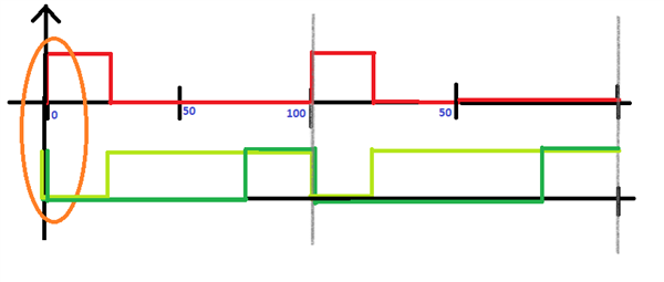
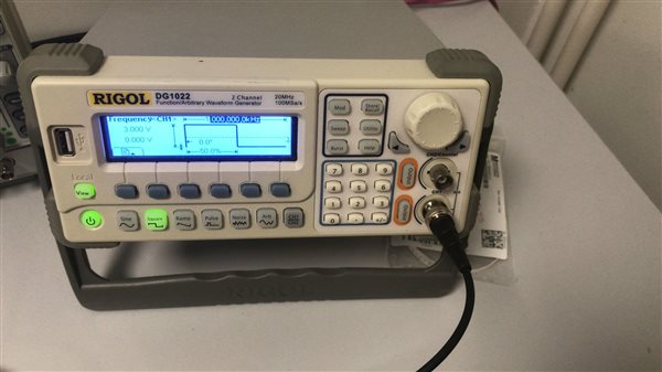
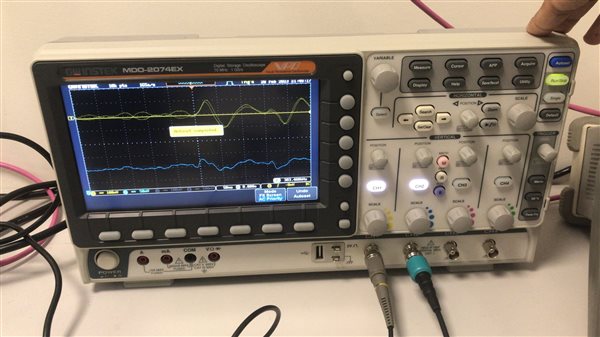
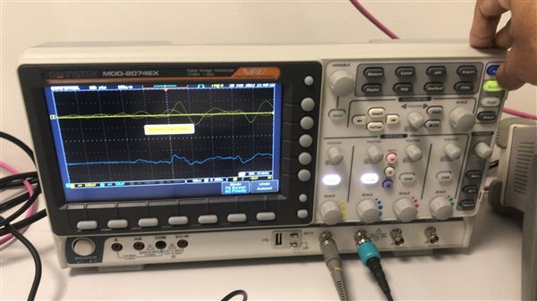
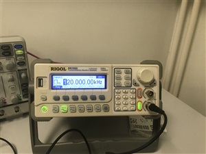
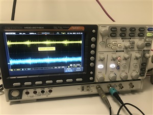
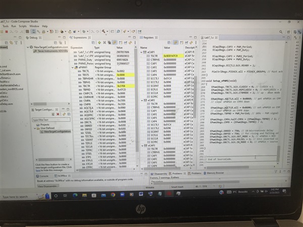
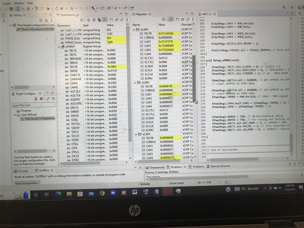
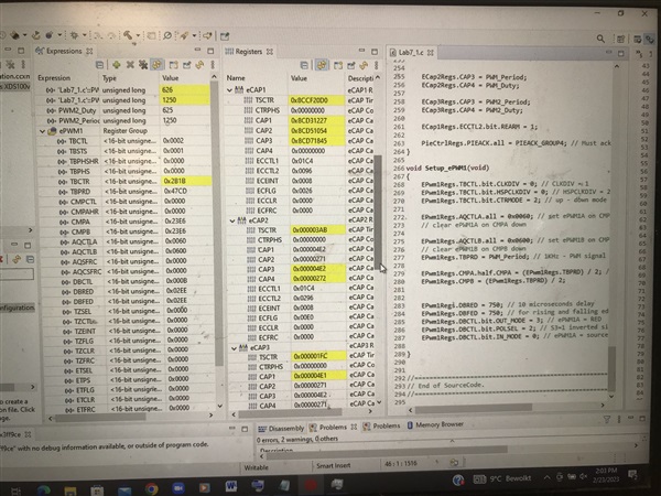
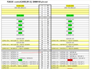
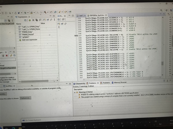
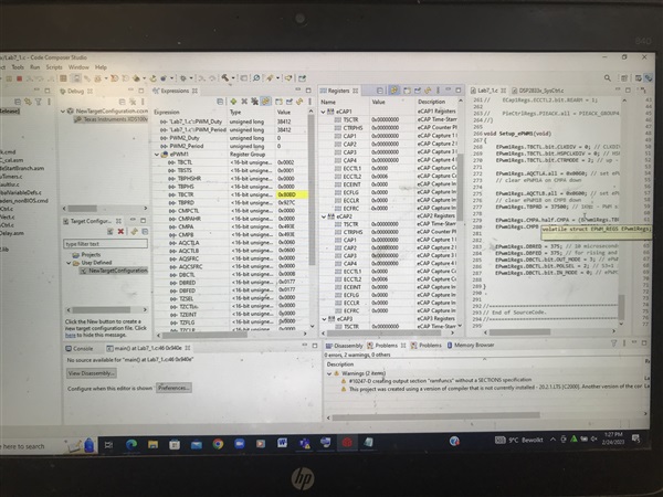
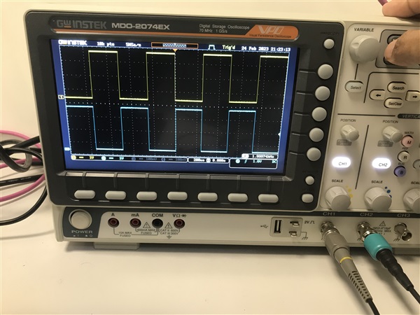
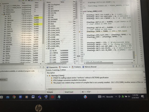
From the Function generator, I captured the square wave(pulses 50Khz & 50% duty cycle) at GPIO24(Ecap) and then generated two APWM signals at GPIO25 & GPIO26(an inversion of GPIO25) using the Ecap module. The signals have controllable variables: PWM_Period, PWM2_Period==> (for Period) and PWM_Duty, PWM2_Duty(for duty cycle). I need to generate a deadband in both GPIO25 & GPIO26 signals. Suppose we multiply any factor say 0.5 with PWM_Period and 0.25 with PWM_Duty. It gives me output 100Khz and duty cycles(25% & 75% for inverted). Here in the above picture, the light green is the inverted signal (25%), Dark green is the factorized duty cycle(75%). The problem is that signal always start at same level (Orange) which creates the current shoot-through problem. How can I create rising and falling edge deadband for the signals in the code? Please suggest in the code.
Regards
Arsalan