This thread has been locked.

If you have a related question, please click the "Ask a related question" button in the top right corner. The newly created question will be automatically linked to this question.

LAUNCHXL-F28379D: I2C with SysConfig -- No STOP Condition

Part Number: LAUNCHXL-F28379D
Other Parts Discussed in Thread: SYSCONFIG, C2000WARE

Hello,

I want to use the I2C module on 379D.

I considered the i2c_ex1_loopback example, but could not download it directly (problem of compilation when changing the package and sekecting the appropriate pins for SDA and SCL).

I recreated the loopback with SysConfig

- Transmitter mode

-  8 bits per data byte

- Data count = 2 (repeat mode OFF by default)

- Target Adress = 0x2

- Own Adress = 0x01

- Loopbackmode = ON

- FIFO mode

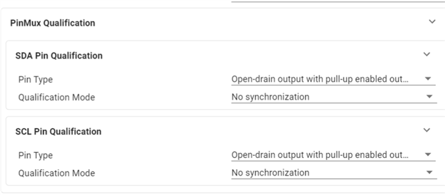
- Open drain with pull up
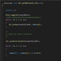
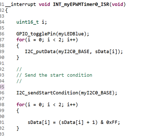
On a timer overflow, I send a put data in the buffer, send a start condition then prepare data for the next time
I read the received data in the FIFO interrupt:
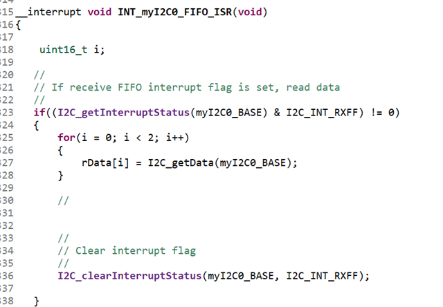
I never send a Stop Condition because this has to be automatically generated in the non repeat mode after 2 transmitted bytes 

I was surprised because after the first two transmitted bytes, the SCL never goes back to the High level   (orange curve down below)

When connecting a digital analyzer, I actually never see any Stop Condition:

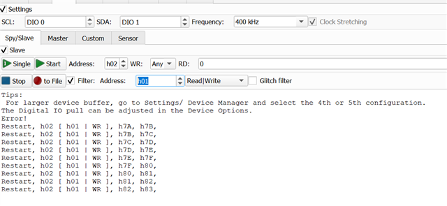
When desactivating the Loopback, and asking to the analyzer to be a slave (0x02), this slave cannot ACKnowledge the Master message:
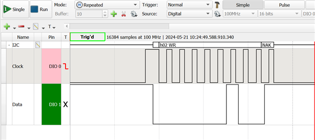
It seems to be a problem with pull up resistors:
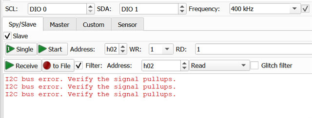
Can somebody help me ?

Thank you

  • Hi Vincent

    I considered the i2c_ex1_loopback example, but could not download it directly (problem of compilation when changing the package and sekecting the appropriate pins for SDA and SCL).

    Between C2000Ware packages, there should be no compilation errors if you have selected the same devices and using I2C specific pins. I would recommend making sure you are always using the latest release for your development, if that is an option.

    In addition to the internal pull-up resistor, I2C requires an external pull resistor. Refer to this App Note on Selecting Pull Resistors as well as past resolved E2Es that have talked about the same. In the I2C TRM section, we've recommended a resistor value of 2.2 kOhms.

    Best Regards,

    Aishwarya

  • Hello Aishwarya,

    Thank you for answering me.

    Thank you for the App Note, I will try with external resistors.

    But I want to understand why the internal resistors does not work, and only for the SCL (no problem on SDA): even if the value is not the best one, considering response time for instance, why SCL line does not come back on the High level after the ACK ? Before any transmission, the idle state is High.

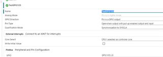
    Is the configuration down below the one I have to choose ?

    edit: I confirm: this is not a pull up issue. With an external pull up, it does the same. I tried to disconnect the internal pull up, it does the same to. So I think that the mico controller pull the SCL to GND for a reason I do not understand

    edit bis: the problem with TI example is not the compilation, but the switch of of packaging within SysConfig (unable to use GPIO ... I did not look further)

  • Vincent,

    I2C (as well as PMBus) use open drain pins which can only drive communications low. Pull-up resistors on both the SDA and SCL pull the lines high when they are not actively being driven low by the open drain configuration, assuming that the high and low-level voltages of SDA/SCL are correct (found in datasheet). Make sure you are using both the internal and external pull-up. For more information, please refer to the many resources on TI about I2C including the shared App Note. In terms of GPIO configuration, your SysConfig settings look correct.

    edit bis: the problem with TI example is not the compilation, but the switch of of packaging within SysConfig (unable to use GPIO ... I did not look further)

    Refer to this thread on how to resolve the SysConfig related issue: (+) TMS320F280025C: SysConfig: Embedded CLI parameters not working

    Best Regards,

    Aishwarya

  • I2C (as well as PMBus) use open drain pins which can only drive communications low. Pull-up resistors on both the SDA and SCL pull the lines high when they are not actively being driven low by the open drain configuration, assuming that the high and low-level voltages of SDA/SCL are correct (found in datasheet)

    Of course I know the purpose of the open drain

    Make sure you are using both the internal and external pull-up. For more information, please refer to the many resources on TI about I2C including the shared App Note

    You tell me how but you don t tell me why. Why do we have to connect both ? I did not see the explanation in the shared App Note (sorry if I missed this detail when readind it)

    Of course I followed your advice, but again, It did the same: see below, SCL never goes back to High level

    I managed to put the TI example into the launchxl, but unfortunately, the communication is continous, with restart condition. I cannot see anny STop Condition

    So, I really think I did not understand something important in the software, not in the hardware.

    I join my own example, if you have time to take a look (you can directly run it on a LANCHXL)

    Thank you for supporting me. Vincent.

    7823.TISupport.zip

  • Hello Aishwarya,

    I really hoped I had some answer today ... I wonder if I was not clear enough.

    I think we can progress by answering to this question: why do we cannot see any Stop condition in the TI example ?

  • Hi Vincent,

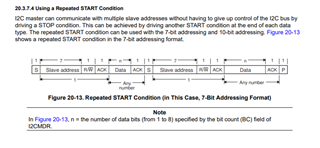
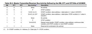
    Thanks for your patience. In the case of this non-repeat mode (RM = 0), I2CCNT is used to generate the STOP condition, so ARDY gets set only when I2CCNT equals 0. As soon as the I2C gets a NACK condition, the ARDY bit gets set immediately. Another thing I would have looked at is the repeated start condition but looks like the bit count is set to 8 and you are transmitting 8 bits.

    In addition, it looks like in response to the NACK, the hardware resets the I2CMDR.STP, by setting the I2CSTR.NACK bit and holding the SCL low. Try setting the I2CMDR.STP to release the SCL as this is the correct way to handle this event.

    Best Regards,

    Aishwarya

  • Hello,

    I am not sure I undestood you correctly. 

    I modified the TI example to be sure that there is no NACK. Instead of sending datas continously, I ask for I2C module to send 2 bytes each 896ms:

    - fill buffer with 2 bytes

    - start condition to send 2 bytes

    After the first frame, as I said, the SCL is holded low:

    I cannot see any NACK.

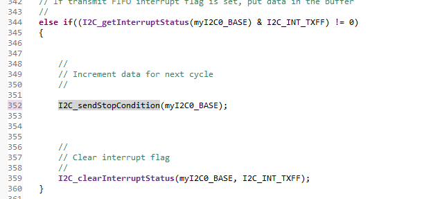
    What you propose is to request for a Stop Condition. Normally I do not have to do so. If want to, I have to be sure that datas are transmitted. So I tried just in the FIFO empty interrupt:

    So, I join my example. It is quit the same as the TI one.

    Can you take a look and tell me where is the error ?

    This works for the first frame, but the communication ends.

    I can understand that TI cannot spend some time looking at user's code. So, if you don't, can you run the TI example "lookback" on a LAUNCHXL379D, and tell me if you can see that SLC is holded low, and tell me why ? 

    Thank you.

    TISupport_v2.zip

  • Vincent,

    Some things that stood out this second version of the code:

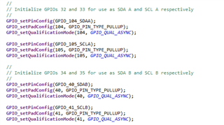
    • Please revert your GPIO configurations back to the original screenshot you sent me. GPIOs of the synchronous communications peripherals should not be qualified as synchronous as described in the GPIO and I2C sections.
    • I see that you are using FIFOs, so the INT_myI2C0_ISR is not necessary.
    • I see that you are using the I2C_putData to transmit data in the EPWM Timer ISR to send data every 896ms, but can you point me to how are you checking that the I2C is actually ready to transmit at this point? This is typically where the TXFF flag is used to indicate transmit ready in FIFO mode. I think the issue may be that if you set up a new write before the previous transaction is done and start a new transaction (new START generated), the stop condition gets affected / cancelled.


    I can understand that TI cannot spend some time looking at user's code. So, if you don't, can you run the TI example "lookback" on a LAUNCHXL379D, and tell me if you can see that SLC is holded low, and tell me why ? 

    As for the standalone i2c_ex1_loopback example, there is no stop condition because it is an infinite loop of back-and-forth data transmissions. This is how the example was presentedWhen modifying the infinite loop to send some finite data packets and send stop condition manually, this should result in a stop condition which is what you saw in your last response. In addition, the emulation modes are different between the example, and your configuration, so what you're seeing when debugging is bound to be different.

    Best Regards,

    Aishwarya

  • Hello,

    Please see down here my answers to your notes:

    Please revert your GPIO configurations back to the original screenshot you sent me. GPIOs of the synchronous communications peripherals should not be qualified as synchronous as described in the GPIO and I2C sections

    Of course I tried this before. It does not change anything

    I see that you are using FIFOs, so the INT_myI2C0_ISR is not necessary

    I agree. But to use FIFO interrupts with SysConfig, I am forced to declare "use Interrupts". Then I can enable interrupts and FIFO interrupts. I do not enable any I2C interrupts but FIFO, although the ISR is defined.

    see that you are using the I2C_putData to transmit data in the EPWM Timer ISR to send data every 896ms, but can you point me to how are you checking that the I2C is actually ready to transmit at this point? This is typically where the TXFF flag is used to indicate transmit ready in FIFO mode. I think the issue may be that if you set up a new write before the previous transaction is done and start a new transaction (new START generated), the stop condition gets affected / cancelled

    I  worked on it. You will find an other version of my application attached to this reply:

    - on Timer interrupt I look if a Flag is set. If yes I load data in the FIFO buffer and lauch a start condition

    - the lookback mode is enabled, and read data in the FIFO Receive interrupt

    - in the FIFO transmitt interrupt (when FIFO is empty), I set the Flag for a new load

    Normally, I do not have to generate any Stop Condition manually

    Still, the SCL signal never goes back to High level.

    As for the standalone i2c_ex1_loopback example, there is no stop condition because it is an infinite loop of back-and-forth data transmissions. This is how the example was presentedWhen modifying the infinite loop to send some finite data packets and send stop condition manually, this should result in a stop condition which is what you saw in your last response. In addition, the emulation modes are different between the example, and your configuration, so what you're seeing when debugging is bound to be different.

    Again, normally there is no stop condition to put in this example. If I am wrong, can you tell me why ?

    Can TI provide me an simple example with a non repeat mode on which I can see SCL going back to High level? (please look at the signals after dowloading the programm into the LAUNCHXL). I have to be sure that I can use I2C with TI tools in my project ?

    Is there a problem with SysConfig or DriverLib ?

    TISupport_v3.zip

  • Vincent,

    I've reached out to our other I2C experts, and hope to get back to you within a day or two.

    Can TI provide me an simple example with a non repeat mode on which I can see SCL going back to High level? (please look at the signals after dowloading the programm into the LAUNCHXL). I have to be sure that I can use I2C with TI tools in my project ?

    Again, this issue is typically the result of weak pull-ups and/or improper clock rate, but as you've mentioned the 2.2-4.7 kOhms resistors did not solve the issue and there were no visible timing issues / code conflicts.

    A non-repeat mode example would simply be modifying the infinite loop to some finite data packets and adding a stop condition manually which you've already done. The examples in C2000Ware are all what we provide. I would recommend searching the forum for more examples as people post their I2C code that may be helpful as well.

    Is there a problem with SysConfig or DriverLib ?

    Is there a specific function or feature you are referring to?

    Best Regards,

    Aishwarya

  • Another suggestion, in the ISR, along with checking for the appropriate flags being set, check to see if the buffer is empty or not by reading the status register. Abnormal I2C communication is possible if data is sent / received before the bus is ready. 

    This works for the first frame, but the communication ends.

    Ultimately, the way to generate a STOP condition is when that I2CMDR.STP condition bit is set. Otherwise, the I2C will not do anything when that I2CCNT reaches zero. In the case of this code snippet that works only for the first frame, that makes sense, because the configuration is non-repeat mode and for only transmitting two bytes. If you want to send multiple 2-bytes at a time, the configuration has to be repeat START mode. In other words, what you're seeing is consistent with what the configurations are.

    In terms of the I2C loopback example, let me check again to see that the waveforms are correct, though I haven't seen any issue with them in the past. Thanks for your patience.

    Best Regards,

    Aishwarya

  • In terms of the I2C loopback example, let me check again to see that the waveforms are correct, though I haven't seen any issue with them in the past. Thanks for your patience

    Thank you. I let you come back to me. I have about 10 days to control this peripheral

  • Vincent,

    By Friday, I can definitely send you over what I’m seeing on the scope for example 3.. Since example 1 is internal loopback, I cannot scope it directly. Will get back to you.

    Best Regards,

    Aishwarya 

  • Hello,

    In the Example 1, you only have to set the pinmux as followed:

    Loopback is very usefull because you ll not need to have any slave to acknowledge the frames

  • Vincent,

    What C2000Ware, CCS, and device package on SysConfig are you using? Using C2000Ware 5.02, CCS 12.7, and default 100PTP, I am only seeing the following options:

    Best Regards,

    Aishwarya

  • Hello. As I said, I use LAUNCHXL379D. So my package is:

    Also, you have to upgrade your  version of C200Ware to 5.02, because 5.01 do not allow to configure the outputs as Open Drain

  • Hello Aishwarya,

    Do you have any news to provide to me concerning this issue ?

    Thanks. Vincent

  • Vincent,

    I tested the example, but I'm unable to replicate the issue. What changes did you make to the example hardware/software wise to be able to scope and see what you're seeing?

    Best Regards,

    Aishwarya

  • Hello,

    I did not change anything in TI example but the pinmux. I join this example in this issue. Since the communication runs continously, how can you see that SCL comes back to High Level ? Can you provide a screen shot of your oscillo ?

    Since you can run the test on a LAUNCHXL, can you download MY example (provided in this reply too), and tell me if the SCL comes back to High level ? (this example is quite the same as TI, but there is a pause between 2 communication) ?

    Can you just modify the TI example by inserting a pause, for me to see the return of SCL to the high level ?

    Thank you for your help.

    Vincent

    2024_06_19_LIEBExample.zip2024_06_19_TIExample.zip

  • Vincent,

    Attached my scope shots below, I used the same setup that you explained to me. I also tried this using multiple LP, so this shows me the issue is not with the SW example. I'll also note that no external pull-ups were used

    Can you try these steps as well to help us resolve this issue:

    1. Try the same loopback example with I2CB. 
    2. Use the GPIO toggle example (gpio_ex2_toggle) to test I2CA and I2CB GPIOs to ensure the GPIOs themselves are working.

    If I2CB passes but not I2CA, there could be an issue with I2CA GPIOs and vice versa. If neither or both works, then the issue is something else.

    Best Regards,

    Aishwarya

  • Hello,

    Thank you for connecting a microcontroller to test it.

    Which example did you use ? It seems to be not Example provided by TI Website, becauise there is a pause between 2 frames.

    If it is not my example, can you send it to me ? Can you test the example I provided ? (just test, I don't ask you to debug my code)

    If you downloaded my example, can you tell me if you use a LAUNCHXL379D ?

    I also try every thing you propose, on two different LAUNCHXL:

    - I cannot see any signal using I2CB module (GPIO02 and 03 or 40 and 41)

    - I see exactly the same using I2CA with GPIO0 and GPIO1

  • Vincent,

    As I mentioned already, this is the I2C EX1 Loopback example from C2000Ware 5.02 that I reinstalled for this thread. I even rewrote the code to not use SysConfig (manually use driverlib functions), and I still do not see any issues. I've attached if you want to try it, it's called ex3, but it is example 1.The GPIO toggle examples also work for all the I2C GPIOs supported by the LP.

    In the GPIO examples do you see the correct values in the registers? This might be already ok, but make sure you are scoping the right headers associated with the GPIOs. 

    Best Regards,

    Aishwarya

    i2c_ex3_external_loopback.zip

    //#############################################################################
    //
    // FILE:   i2c_ex1_loopback.c
    //
    // TITLE:  I2C Digital Loopback with FIFO Interrupts
    //
    //! \addtogroup driver_example_list
    //! <h1>I2C Digital Loopback with FIFO Interrupts</h1>
    //!
    //! This program uses the internal loopback test mode of the I2C module. Both
    //! the TX and RX I2C FIFOs and their interrupts are used. The pinmux and I2C
    //! initialization is done through the sysconfig file.
    //!
    //! A stream of data is sent and then compared to the received stream.
    //! The sent data looks like this: \n
    //!  0000 0001 \n
    //!  0001 0002 \n
    //!  0002 0003 \n
    //!  .... \n
    //!  00FE 00FF \n
    //!  00FF 0000 \n
    //!  etc.. \n
    //! This pattern is repeated forever.
    //!
    //! \b External \b Connections \n
    //!  - None
    //!
    //! \b Watch \b Variables \n
    //!  - \b sData - Data to send
    //!  - \b rData - Received data
    //!  - \b rDataPoint - Used to keep track of the last position in the receive
    //!    stream for error checking
    //!
    //
    //#############################################################################
    //
    // 
    // $Copyright:
    // Copyright (C) 2013-2024 Texas Instruments Incorporated - http://www.ti.com/
    //
    // Redistribution and use in source and binary forms, with or without 
    // modification, are permitted provided that the following conditions 
    // are met:
    // 
    //   Redistributions of source code must retain the above copyright 
    //   notice, this list of conditions and the following disclaimer.
    // 
    //   Redistributions in binary form must reproduce the above copyright
    //   notice, this list of conditions and the following disclaimer in the 
    //   documentation and/or other materials provided with the   
    //   distribution.
    // 
    //   Neither the name of Texas Instruments Incorporated nor the names of
    //   its contributors may be used to endorse or promote products derived
    //   from this software without specific prior written permission.
    // 
    // THIS SOFTWARE IS PROVIDED BY THE COPYRIGHT HOLDERS AND CONTRIBUTORS 
    // "AS IS" AND ANY EXPRESS OR IMPLIED WARRANTIES, INCLUDING, BUT NOT 
    // LIMITED TO, THE IMPLIED WARRANTIES OF MERCHANTABILITY AND FITNESS FOR
    // A PARTICULAR PURPOSE ARE DISCLAIMED. IN NO EVENT SHALL THE COPYRIGHT 
    // OWNER OR CONTRIBUTORS BE LIABLE FOR ANY DIRECT, INDIRECT, INCIDENTAL, 
    // SPECIAL, EXEMPLARY, OR CONSEQUENTIAL DAMAGES (INCLUDING, BUT NOT 
    // LIMITED TO, PROCUREMENT OF SUBSTITUTE GOODS OR SERVICES; LOSS OF USE,
    // DATA, OR PROFITS; OR BUSINESS INTERRUPTION) HOWEVER CAUSED AND ON ANY
    // THEORY OF LIABILITY, WHETHER IN CONTRACT, STRICT LIABILITY, OR TORT 
    // (INCLUDING NEGLIGENCE OR OTHERWISE) ARISING IN ANY WAY OUT OF THE USE 
    // OF THIS SOFTWARE, EVEN IF ADVISED OF THE POSSIBILITY OF SUCH DAMAGE.
    // $
    //#############################################################################
    
    //
    // Included Files
    //
    #include "driverlib.h"
    #include "device.h"
    //#include "board.h"
    
    //
    // Defines
    //
    #define SLAVE_ADDRESS   0x3C
    
    //
    // Globals
    //
    uint16_t sData[2];                  // Send data buffer
    uint16_t rData[2];                  // Receive data buffer
    uint16_t rDataPoint = 0;            // To keep track of where we are in the
                                        // data stream to check received data
    
    //
    // Function Prototypes
    //
    __interrupt void i2cFIFOISR(void);
    void I2C_init(void);
    void myI2C0_init(void);
    
    //
    // Main
    //
    void main(void)
    {
        uint16_t i;
    
        //
        // Initialize device clock and peripherals
        //
        Device_init();
    
        //
        // Disable pin locks and enable internal pullups.
        //
        Device_initGPIO();
    
        GPIO_setPinConfig(GPIO_104_SDAA);
        GPIO_setPadConfig(104, GPIO_PIN_TYPE_OD | GPIO_PIN_TYPE_PULLUP);
        GPIO_setQualificationMode(104, GPIO_QUAL_ASYNC);
    
        GPIO_setPinConfig(GPIO_105_SCLA);
        GPIO_setPadConfig(105, GPIO_PIN_TYPE_OD | GPIO_PIN_TYPE_PULLUP);
        GPIO_setQualificationMode(105, GPIO_QUAL_ASYNC);
    
        //
        // Initialize PIE and clear PIE registers. Disables CPU interrupts.
        //
        Interrupt_initModule();
    
        //
        // Initialize the PIE vector table with pointers to the shell Interrupt
        // Service Routines (ISR).
        //
        Interrupt_initVectorTable();
    
        //
        // Board initialization
        //
    //    Board_init();
    
            EALLOW;
    
    //        PinMux_init();
            I2C_init();
    
            EDIS;
    
        GPIO_setDirectionMode(104, GPIO_DIR_MODE_OUT);
        GPIO_setDirectionMode(105, GPIO_DIR_MODE_OUT);
    
        //
        // For loopback mode only
        //
        I2C_setOwnSlaveAddress(I2CA_BASE, SLAVE_ADDRESS);
    
        //
        // Interrupts that are used in this example are re-mapped to ISR functions
        // found within this file.
        //
        Interrupt_register(INT_I2CA_FIFO, &i2cFIFOISR);
    
        //
        // Initialize the data buffers
        //
        for(i = 0; i < 2; i++)
        {
            sData[i] = i;
            rData[i]= 0;
        }
    
        //
        // Enable interrupts required for this example
        //
        Interrupt_enable(INT_I2CA_FIFO);
    
        //
        // Enable Global Interrupt (INTM) and realtime interrupt (DBGM)
        //
        EINT;
        ERTM;
    
        //
        // Loop forever. Suspend or place breakpoints to observe the buffers.
        //
        while(1)
        {
         // A FIFO interrupt will be generated for each Tx and Rx based
         // on the Interrupt levels configured.
         // The ISR will handle pushing/pulling data to/from the TX and
         // RX FIFOs resp.
        }
    
    }
    
    void PinMux_init()
    {
        //
        // PinMux for modules assigned to CPU1
        //
    
        //
        // I2CA -> myI2C0 Pinmux
        //
        GPIO_setPinConfig(GPIO_104_SDAA);
        GPIO_setPadConfig(104, GPIO_PIN_TYPE_OD | GPIO_PIN_TYPE_PULLUP);
        GPIO_setQualificationMode(104, GPIO_QUAL_ASYNC);
    
        GPIO_setPinConfig(GPIO_105_SCLA);
        GPIO_setPadConfig(105, GPIO_PIN_TYPE_OD | GPIO_PIN_TYPE_PULLUP);
        GPIO_setQualificationMode(105, GPIO_QUAL_ASYNC);
    
    
    }
    
    //*****************************************************************************
    //
    // I2C Configurations
    //
    //*****************************************************************************
    void I2C_init(){
        myI2C0_init();
    }
    
    void myI2C0_init(){
        I2C_disableModule(I2CA_BASE);
        I2C_initController(I2CA_BASE, DEVICE_SYSCLK_FREQ, 400000, I2C_DUTYCYCLE_50);
        I2C_setConfig(I2CA_BASE, I2C_CONTROLLER_SEND_MODE);
        I2C_enableLoopback(I2CA_BASE);
        I2C_setOwnAddress(I2CA_BASE, 0);
        I2C_setOwnAddress(I2CA_BASE, 0);
        I2C_setTargetAddress(I2CA_BASE, 60);
        I2C_setBitCount(I2CA_BASE, I2C_BITCOUNT_8);
        I2C_setDataCount(I2CA_BASE, 2);
        I2C_setAddressMode(I2CA_BASE, I2C_ADDR_MODE_7BITS);
        I2C_enableFIFO(I2CA_BASE);
        I2C_clearInterruptStatus(I2CA_BASE, I2C_INT_RXFF | I2C_INT_TXFF);
        I2C_setFIFOInterruptLevel(I2CA_BASE, I2C_FIFO_TX2, I2C_FIFO_RX2);
        I2C_enableInterrupt(I2CA_BASE, I2C_INT_RXFF | I2C_INT_TXFF);
        I2C_setEmulationMode(I2CA_BASE, I2C_EMULATION_STOP_SCL_LOW);
        I2C_enableModule(I2CA_BASE);
    }
    
    
    //
    // I2C A Transmit & Receive FIFO ISR.
    //
     __interrupt void i2cFIFOISR(void)
    {
        uint16_t i;
    
        //
        // If receive FIFO interrupt flag is set, read data
        //
        if((I2C_getInterruptStatus(I2CA_BASE) & I2C_INT_RXFF) != 0)
        {
            for(i = 0; i < 2; i++)
            {
                rData[i] = I2C_getData(I2CA_BASE);
            }
    
            //
            // Check received data
            //
            for(i = 0; i < 2; i++)
            {
                if(rData[i] != ((rDataPoint + i) & 0xFF))
                {
                    //
                    // Something went wrong. rData doesn't contain expected data.
                    //
                    ESTOP0;
                }
            }
    
            rDataPoint = (rDataPoint + 1) & 0xFF;
    
            //
            // Clear interrupt flag
            //
            I2C_clearInterruptStatus(I2CA_BASE, I2C_INT_RXFF);
    
        }
        //
        // If transmit FIFO interrupt flag is set, put data in the buffer
        //
        else if((I2C_getInterruptStatus(I2CA_BASE) & I2C_INT_TXFF) != 0)
        {
            for(i = 0; i < 2; i++)
            {
                I2C_putData(I2CA_BASE, sData[i]);
            }
    
            //
            // Send the start condition
            //
            I2C_sendStartCondition(I2CA_BASE);
    
            //
            // Increment data for next cycle
            //
            for(i = 0; i < 2; i++)
            {
               sData[i] = (sData[i] + 1) & 0xFF;
            }
    
            //
            // Clear interrupt flag
            //
            I2C_clearInterruptStatus(I2CA_BASE, I2C_INT_TXFF);
        }
    
        //
        // Issue ACK
        //
        Interrupt_clearACKGroup(INTERRUPT_ACK_GROUP8);
    }
    
    //
    // End of File
    //
    

  • Hello,

    How can you tell that SCL returns back to High Level on this continous example ?

    Also, why did you consider an old example, without SysConfig for instance ? I had just to be sure that there is no problem with SysConfig neither DriverLib.

    Could you just:

    - insert a delay between 2 transmitt in your example, to show me the return to the High level ? (and not the first state)

    - use the example provided on the website ? (with SysConfig)

    - please please please just do the test with the example I provided to you. I don't ask you to debug my code, just to tell me if the SCL is pull to low level.

    Today I cannot see any solution to this problem. It is the first time I have this on a such simple issue :(

  • Vincent,

    Similar to your scope shots showing that the SCL never goes back to the high level, the scope shots I sent show that the SCL does go back to the correct level consistently while running the loop back example. I provided a zoomed version to look at multiple clocks.

    The scope shot is from the example version using SysConfig (from C2000Ware). To be thorough, I also took the generated code from this original example and ran it without SysConfig. Same results.

    I will have access to a launch pad and a scope on Tuesday and can run the example with a delay and your example then. 

    - I cannot see any signal using I2CB module (GPIO02 and 03 or 40 and 41)

    In the meantime, please debug and see why you cannot see the GPIO toggle using the given toggle example for I2CA and I2CB. If the GPIO is not toggling, this might be a different issue. 
    Best Regards,

    Aishwarya 

  • I provided a zoomed version to look at multiple clocks.

    Hello,

    Even if zooming, how can you see any pause before clock is going low ? (honnestly, I thought that your photo was a single acquisition of the first edge)

    There is no pause at all when running your code.

    Do you use a LAUNCHXL379D ?

    Is there any connexion I have to do on this board ?

  • Hi Vincent,

    This expert is currently out of office until 7/1. Please expect a delay in response until then. Thank you for your patience.

    Best Regards,

    Allison

  • Vincent,

    I got ahold of a LP and will run the code on it today.

    As for my original setup when running the example as is, I used no external connections on the LAUNCHXL379D except to scope the IOs. There is no pause in this loopback example which continually loops in software.

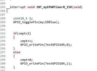
    Also, can you confirm if the GPIO toggle example works on all the I2C IOs. This confirmation is needed to rule out GPIO connection issues.

    Best Regards,
    Aishwarya

  • Hello.

    As you asked to me, I tested the GPIO105, the  one which is used for SCL

    - open drain with Pull up

    - directly in the application, disabling the outputs of I2CA, and ask for a nlinking of the GPIO

    Everything is fine.

    There is no pause in this loopback example which continually loops in software.

    Again, since there is no pause, the screenshot you sent to me is impossible to see, but just before the first transmission. What is important to see is not that the SCL goes from High to Low at the begeinning of this transmission, but that it goes from low to high at its end.

    I m glad that you re about to load the code into the LP. I was afrais that you will not help me anymore.

    I hope I will speak you soon.

    Have a nice day.

    Vince

  • Hi Vincent,

    I will get back to you with my response on Monday, July 8th. Thank you for your understanding.

    Aishwarya

  • Hi Vincent,

    Aishwarya is located in a region affected by the Hurricane Beryl and may not be able to respond for the next 2-3 days. Please expect a delay in response till the time she is back. Thanks for understanding.  

  • Vincent,

    Thanks for your patience. I won't be able to debug your code beyond the debugging I've provided for the C2000Ware software examples. At this point, I would recommend running and scoping out i2c_ex3_external_loopback to see what the results are. 

    I am going to loop in our software experts who can answer your specific question of why this example is written the way that it is. Please expect an answer in 1-2 days.

    Best Regards,

    Aishwarya

  • Hello,

    I hope you had not serious problems with the hurricane.

    I will wait for the answer of your experts. Thank you

  • Vincent,

    Thank you. I will be out of office the next few days but have followed up with our I2C software expert.

    Best Regards,

    Aishwarya

  • Hello, sorry to bother you but nobody came back to me. I don't know if I must wait a answer from TI. This problem will get serious ...

    Could you check that one of your expert took my issue into account ?

    Many thanks.

    Vince

  • Vincent,

    I have followed up with our I2C software expert again.

    Best Regards,

    Aishwarya

  • Vince

    This is the waveform thar we observed after running with this C file (/cfs-file/__key/communityserver-discussions-components-files/171/modified_5F00_ex.c ),

    we see that the SCL pin goes high after the transfer.  

    Best Regards

    Siddharth

  • Hello.

    First I want to thank you for coming back to me.

    I did not try yet, I hope I will be able to test it before my vacation (wensday). Just to help me to going on faster: must have to replace the C main file in the TI example by this one to see the idle state of SCL ? What did you modify ?

    I have to use SysConfig for this project (this is important for us) So, if this example works on the LAUNCHXL, I will use Sysconfig and see if generated DriverLib Command will be the same. Any advice ?

    Speak you soon. Vince.

  • Hello Siddharth,

    I tried to run the example You sent to me.

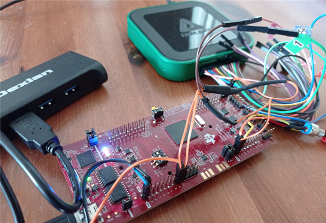
    I just change the PinMux and the PinConfig to make it runable on the LaunchXL (all the GPIOs are not available ont the demoboard)

    What I understood is that you send a first frame with I2CA just to check that the SCL goes back to High Level. 

    You don't use the rest of the programm.

    So, I ask my oscilloscope to trig one on an edge of SCL, and ran your programm in the debug mode:

    The SCL does not go back to high level.

    But, also, the programm stops at ESTOP, although I connected GPIO40 to GPIO104 and GPIO41 to GPIO105:

    Can you test your programm on LAUNCHXL379D ?

    Many thanks

  • Hello Siddarth,

    Did you see my previous answer ?

    I am sorry to bother you, but are you able to test your programm as I did on a LAUNCHXL ?

    Many Thanks.

    Vince.