This thread has been locked.

If you have a related question, please click the "Ask a related question" button in the top right corner. The newly created question will be automatically linked to this question.

TMDXIDDK379D: Some confusion about the extended use of the SDFM module

Part Number: TMDXIDDK379D
Other Parts Discussed in Thread: C2000WARE

  Hi,

  Ti friends!

  The client is currently doing some development based on the SDFM module and has some questions to ask:
1. Can it be realised that the SDFM module is sampled some time before the triangular carrier underflow point, i.e. when it is 0. If it can be realised, where can the official kit code be modified?
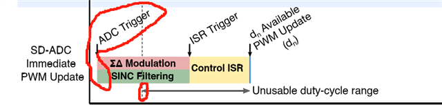
2.The client is currently doing some development based on the SDFM module and has some questions to ask:
1. Can it be realised that the SDFM module is sampled some time before the triangular carrier underflow point, i.e. when it is 0. If it can be realised, where can the official kit code be modified?
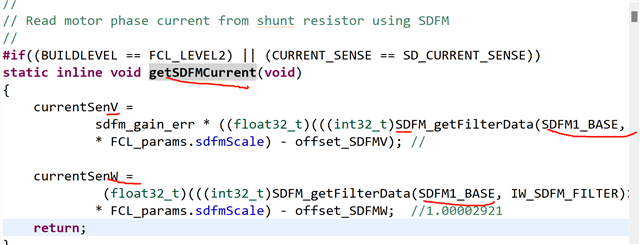
2. According to the official routine, using the SDFM1 address sampling phase current sampling for V,W phase, can we get the following sampling form, that is, sampling once, to obtain two OSR different filter output phase current V,W it, and then subsequently according to the requirements of the selection of a group of phase current for closed-loop control?

Thanks for your help!

  • HI,

    1. Can it be realised that the SDFM module is sampled some time before the triangular carrier underflow point, i.e. when it is 0. If it can be realised, where can the official kit code be modified?

    I'm familiar with 'carrier underflow point', what is the application? 

    According to the official routine, using the SDFM1 address sampling phase current sampling for V,W phase, can we get the following sampling form, that is, sampling once, to obtain two OSR different filter output phase current V,W it, and then subsequently according to the requirements of the selection of a group of phase current for closed-loop control?

    Are you using a TI reference design? If so, could you let me know which one? 

    Best Regards,

    Ben Collier

  • 1.The start of the ∑-Δ sampling is triggered at the moment τd before the arrival of the synchronisation signal . This corresponds exactly to the midpoint of the sampling sequence to the synchronisation signal setup.

    2.The current kit used is tmdxiddk379d for motor control, and the supporting code is located at C:\ti\c2000\C2000Ware_MotorControl_SDK_3_02_00_00\solutions\tmdxiddk379d, a fast current loop based on the FCL

  • Hi Bob,

    There are newer versions of the MCSDK, up to v5_02 now. It might be good download and use the latest since there are updates to the code. I don't have v3_02 installed, so I can't see the exact same code you're showing.

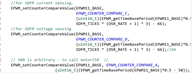
    PWM sync to SDFM can be altered by changing the compare values, initialized in the code section below:

        //for SDFM current sensing
        EPWM_setCounterCompareValue(EPWM11_BASE,
                                    EPWM_COUNTER_COMPARE_C,
                                    (uint16_t)(EPWM_getTimeBasePeriod(EPWM11_BASE) -
                                    SDFM_TICKS * (OSR_RATE + 1) * 3 / 2));
        //for SDFM voltage sensing
        EPWM_setCounterCompareValue(EPWM11_BASE,
                                    EPWM_COUNTER_COMPARE_D,
                                    (uint16_t)(EPWM_getTimeBasePeriod(EPWM11_BASE) -
                                    SDFM_TICKS * (OSR_RATE + 1) * 3 / 2));

    1.The start of the ∑-Δ sampling is triggered at the moment τd before the arrival of the synchronisation signal . This corresponds exactly to the midpoint of the sampling sequence to the synchronisation signal setup.

    I'm not able to follow your point here, sorry. This prior post may help clarify some things for you however: https://e2e.ti.com/support/microcontrollers/c2000-microcontrollers-group/c2000/f/c2000-microcontrollers-forum/897922/ccs-tms320f280049-sdfm-pwm-sync-problem?tisearch=e2e-sitesearch&keymatch=AMC1035 

    Best,

    Kevin
