

Other Parts Discussed in Thread: TMS320F28035, CCSTUDIO, CONTROLSUITE, TMS320F28335
What's the easiest way to implement FAT library out there that will fit in the small 128-KB flash of TMS320F28035? All I need is read and write in FAT16.
Thanks

This thread has been locked.
If you have a related question, please click the "Ask a related question" button in the top right corner. The newly created question will be automatically linked to this question.
Other Parts Discussed in Thread: TMS320F28035, CCSTUDIO, CONTROLSUITE, TMS320F28335
What's the easiest way to implement FAT library out there that will fit in the small 128-KB flash of TMS320F28035? All I need is read and write in FAT16.
Thanks
Gloria,
There are several FAT stacks out there that will fit in the flash of the 2803x devices. FATFS is the one we use and it has a smaller derivative called Petite FATFS.
It appears the webpage has been taken down, but it is still available in the Google Cached copy:
I also zipped up a copy of the version we use with the 2806x devices. This should port over without any major modifications to the 2803x devices.
Hope this helps!
Trey German
C2000 Software Applications


Gloria,
I notice a few things that I am concerned about in the linker output.
Let me know if this helps or if you have further questions.
Trey German
HI,
I have installed control Suite and that has cleared up the first problem of the cmd linker file. However, for some reason mmc-c28x.c is not wanting to link to the right library. I'm using CCS3.3, the program that came with the micro controller. Is there a way to make CSS3 link to the library in
C:\TI\controlSUITE\device_support\f2803x\version\DSP2803x_common\cmd
Thank you,
Alex
Alex,
I'm not sure I fully understand your problem. If you compile mmc-c28x.c with your project it will automatically be linked in to your project. Could you further elaborate on the problem you are having?
I should have also mentioned earlier that I made the assumption that you wanted to talk to an SD card with your filesystem. The mmc-c28x.c file is a driver for the SPI peripheral that allows the FAT filesystem to talk to the SD card. If you intend to access a filesystem that isn't on an SD card you will need to provide your own driver file.
Trey
Actually, what we need is capability to read from and write to SD card formatted in FAT32 filesystem. If we do need our own driver file, is there any pointer on how to implement this?
Thanks
Alex,
This software will do that. The SD card will connect to the micro through SPI and then you will use ff.c or tff.c (smaller memory footprint) along with mmc-c28x.c. mmc-c28x.c provides drivers for ff.c to access the SPI peripheral.
I've attached an example application. This was originally written for a Cortex M3 device and will not run as is on a C28x device. It should provide a good example of how to use FatFS, and with a few modifications it should run on your device.
//###########################################################################
// FILE:   sd_card.c
// TITLE:  Example program for reading files from an SD card.
//###########################################################################
// $TI Release: F28M35x Driver Library vBeta1 $
// $Release Date: August 31, 2011 $
//###########################################################################

#include <string.h>
#include "inc/hw_ints.h"
#include "inc/hw_memmap.h"
#include "inc/hw_nvic.h"
#include "inc/hw_sysctl.h"
#include "inc/hw_types.h"
#include "driverlib/gpio.h"
#include "driverlib/interrupt.h"
#include "driverlib/sysctl.h"
#include "driverlib/systick.h"
#include "utils/cmdline.h"
#include "utils/uartstdio.h"
#include "utils/ustdlib.h"
#include "third_party/fatfs/src/ff.h"
#include "third_party/fatfs/src/diskio.h"

//*****************************************************************************
//! \addtogroup master_example_list
//! <h1>SD card using FAT file system (sd_card)</h1>
//!
//! This example application demonstrates reading a file system from
//! an SD card.  It makes use of FatFs, a FAT file system driver.
//!
//! For additional details about FatFs, see the following site:
//! http://elm-chan.org/fsw/ff/00index_e.html
//!
//! The application may be operated via a serial terminal attached to
//! UART0. The RS232 communication parameters should be set to 115,200 bits
//! per second, and 8-n-1 mode.  When the program is started a message will be
//! printed to the terminal.  Type ``help'' for command help.
//*****************************************************************************

extern void UARTStdioIntHandler(void);

//*****************************************************************************
// Defines the size of the buffers that hold the path, or temporary
// data from the SD card.  There are two buffers allocated of this size.
// The buffer size must be large enough to hold the longest expected
// full path name, including the file name, and a trailing null character.
//*****************************************************************************
#define PATH_BUF_SIZE   80

//*****************************************************************************
// Defines the size of the buffer that holds the command line.
//*****************************************************************************
#define CMD_BUF_SIZE    64

//*****************************************************************************
// This buffer holds the full path to the current working directory.
// Initially it is root ("/").
//*****************************************************************************
static char g_cCwdBuf[PATH_BUF_SIZE] = "/";

//*****************************************************************************
// A temporary data buffer used when manipulating file paths, or reading data
// from the SD card.
//*****************************************************************************
static char g_cTmpBuf[PATH_BUF_SIZE];

//*****************************************************************************
// The buffer that holds the command line.
//*****************************************************************************
static char g_cCmdBuf[CMD_BUF_SIZE];

//*****************************************************************************
// The following are data structures used by FatFs.
//*****************************************************************************
static FATFS g_sFatFs;
static DIR g_sDirObject;
static FILINFO g_sFileInfo;
static FIL g_sFileObject;

//*****************************************************************************
// A structure that holds a mapping between an FRESULT numerical code,
// and a string represenation.  FRESULT codes are returned from the FatFs
// FAT file system driver.
//*****************************************************************************
typedef struct
{
    FRESULT fresult;
    char *pcResultStr;
}
tFresultString;

//*****************************************************************************
// A macro to make it easy to add result codes to the table.
//*****************************************************************************
#define FRESULT_ENTRY(f)        { (f), (# f) }

//*****************************************************************************
// A table that holds a mapping between the numerical FRESULT code and
// it's name as a string.  This is used for looking up error codes for
// printing to the console.
//*****************************************************************************
tFresultString g_sFresultStrings[] =
{
    FRESULT_ENTRY(FR_OK),
    FRESULT_ENTRY(FR_NOT_READY),
    FRESULT_ENTRY(FR_NO_FILE),
    FRESULT_ENTRY(FR_NO_PATH),
    FRESULT_ENTRY(FR_INVALID_NAME),
    FRESULT_ENTRY(FR_INVALID_DRIVE),
    FRESULT_ENTRY(FR_DENIED),
    FRESULT_ENTRY(FR_EXIST),
    FRESULT_ENTRY(FR_RW_ERROR),
    FRESULT_ENTRY(FR_WRITE_PROTECTED),
    FRESULT_ENTRY(FR_NOT_ENABLED),
    FRESULT_ENTRY(FR_NO_FILESYSTEM),
    FRESULT_ENTRY(FR_INVALID_OBJECT),
    FRESULT_ENTRY(FR_MKFS_ABORTED)
};

//*****************************************************************************
// Error reasons returned by ChangeDirectory().
//*****************************************************************************
#define NAME_TOO_LONG_ERROR 1
#define OPENDIR_ERROR       2

//*****************************************************************************
// A macro that holds the number of result codes.
//*****************************************************************************
#define NUM_FRESULT_CODES (sizeof(g_sFresultStrings) / sizeof(tFresultString))

//*****************************************************************************
// The number of SysTick ticks per second.
//*****************************************************************************
#define TICKS_PER_SECOND 100

//*****************************************************************************
// Storage for the filename listbox widget string table.
//*****************************************************************************
#define NUM_LIST_STRINGS 48
const char *g_ppcDirListStrings[NUM_LIST_STRINGS];

//*****************************************************************************
// Storage for the names of the files in the current directory.  Filenames
// are stored in format "(D) filename.ext" for directories or "(F) filename.ext"
// for files.
//*****************************************************************************
#define MAX_FILENAME_STRING_LEN (4 + 8 + 1 + 3 + 1)
char g_pcFilenames[NUM_LIST_STRINGS][MAX_FILENAME_STRING_LEN];

//*****************************************************************************
// Storage for the strings which appear in the status box at the bottom of the
// display.
//****************************************************************************
#define NUM_STATUS_STRINGS 6
#define MAX_STATUS_STRING_LEN (36 + 1)
char g_pcStatus[NUM_STATUS_STRINGS][MAX_STATUS_STRING_LEN];

//*****************************************************************************
// Storage for the status listbox widget string table.
//*****************************************************************************
const char *g_ppcStatusStrings[NUM_STATUS_STRINGS] =
{
    g_pcStatus[0],
    g_pcStatus[1],
    g_pcStatus[2],
    g_pcStatus[3],
    g_pcStatus[4],
    g_pcStatus[5]
};
unsigned long g_ulStatusStringIndex = 0;

//*****************************************************************************
// Forward declarations for functions called by the widgets used in the user
// interface.
//*****************************************************************************
static FRESULT ChangeToDirectory(char *pcDirectory, unsigned long *pulReason);
static const char *StringFromFresult(FRESULT fresult);

//*****************************************************************************
// This function returns a string representation of an error code
// that was returned from a function call to FatFs.  It can be used
// for printing human readable error messages.
//*****************************************************************************
static const char *
StringFromFresult(FRESULT fresult)
{
    unsigned int uIdx;

    // Enter a loop to search the error code table for a matching
    // error code.
    for(uIdx = 0; uIdx < NUM_FRESULT_CODES; uIdx++)
    {
        // If a match is found, then return the string name of the
        // error code.
        if(g_sFresultStrings[uIdx].fresult == fresult)
        {
            return(g_sFresultStrings[uIdx].pcResultStr);
        }
    }

    // At this point no matching code was found, so return a
    // string indicating unknown error.
    return("UNKNOWN ERROR CODE");
}

//*****************************************************************************
// This is the handler for this SysTick interrupt.  FatFs requires a
// timer tick every 10 ms for internal timing purposes.
//*****************************************************************************
void
SysTickHandler(void)
{
    // Call the FatFs tick timer.
    disk_timerproc();
}

//*****************************************************************************
// This function implements the "ls" command.  It opens the current
// directory and enumerates through the contents, and prints a line for
// each item it finds.  It shows details such as file attributes, time and
// date, and the file size, along with the name.  It shows a summary of
// file sizes at the end along with free space.
//*****************************************************************************
int
Cmd_ls(int argc, char *argv[])
{
    unsigned long ulTotalSize, ulItemCount, ulFileCount, ulDirCount;
    FRESULT fresult;
    FATFS *pFatFs;

    // Open the current directory for access.
    fresult = f_opendir(&g_sDirObject, g_cCwdBuf);

    // Check for error and return if there is a problem.
    if(fresult != FR_OK)
    {

        return(fresult);
    }

    ulTotalSize = 0;
    ulFileCount = 0;
    ulDirCount = 0;
    ulItemCount = 0;

    // Give an extra blank line before the listing.
    UARTprintf("\n");

    // Enter loop to enumerate through all directory entries.
    for(;;)
    {
        // Read an entry from the directory.
        fresult = f_readdir(&g_sDirObject, &g_sFileInfo);

        // Check for error and return if there is a problem.
        if(fresult != FR_OK)
        {
            return(fresult);
        }

        // If the file name is blank, then this is the end of the
        // listing.
        if(!g_sFileInfo.fname[0])
        {
            break;
        }

        // Print the entry information on a single line with formatting
        // to show the attributes, date, time, size, and name.
        UARTprintf("%c%c%c%c%c %u/%02u/%02u %02u:%02u %9u  %s\n",
                   (g_sFileInfo.fattrib & AM_DIR) ? 'D' : '-',
                   (g_sFileInfo.fattrib & AM_RDO) ? 'R' : '-',
                   (g_sFileInfo.fattrib & AM_HID) ? 'H' : '-',
                   (g_sFileInfo.fattrib & AM_SYS) ? 'S' : '-',
                   (g_sFileInfo.fattrib & AM_ARC) ? 'A' : '-',
                   (g_sFileInfo.fdate >> 9) + 1980,
                   (g_sFileInfo.fdate >> 5) & 15,
                   g_sFileInfo.fdate & 31,
                   (g_sFileInfo.ftime >> 11),
                   (g_sFileInfo.ftime >> 5) & 63,
                   g_sFileInfo.fsize,
                   g_sFileInfo.fname);

        // Add the information as a line in the listbox widget.
        if(ulItemCount < NUM_LIST_STRINGS)
        {
            usprintf(g_pcFilenames[ulItemCount], "(%c) %12s",
                     (g_sFileInfo.fattrib & AM_DIR) ? 'D' : 'F',
                     g_sFileInfo.fname);
        }

        // If the attribute is directory, then increment the directory count.
        if(g_sFileInfo.fattrib & AM_DIR)
        {
            ulDirCount++;
        }

        // Otherwise, it is a file.  Increment the file count, and
        // add in the file size to the total.
        else
        {
            ulFileCount++;
            ulTotalSize += g_sFileInfo.fsize;
        }

        // Move to the next entry in the item array we use to populate the
        // list box.
        ulItemCount++;

        // Wait for the UART transmit buffer to empty.
        UARTFlushTx(false);

    }   // endfor

    // Print summary lines showing the file, dir, and size totals.
    UARTprintf("\n%4u File(s),%10u bytes total\n%4u Dir(s)",
               ulFileCount, ulTotalSize, ulDirCount);

    // Get the free space.
    fresult = f_getfree("/", &ulTotalSize, &pFatFs);

    // Check for error and return if there is a problem.
    if(fresult != FR_OK)
    {
        return(fresult);
    }

    // Display the amount of free space that was calculated.
    UARTprintf(", %10uK bytes free\n", ulTotalSize * pFatFs->sects_clust / 2);

    // Wait for the UART transmit buffer to empty.
    UARTFlushTx(false);

    // Made it to here, return with no errors.
    return(0);
}

//*****************************************************************************
// This function implements the "cd" command.  It takes an argument
// that specifes the directory to make the current working directory.
// Path separators must use a forward slash "/".  The argument to cd
// can be one of the following:
// * root ("/")
// * a fully specified path ("/my/path/to/mydir")
// * a single directory name that is in the current directory ("mydir")
// * parent directory ("..")
// It does not understand relative paths, so dont try something like this:
// ("../my/new/path")
// Once the new directory is specified, it attempts to open the directory
// to make sure it exists.  If the new path is opened successfully, then
// the current working directory (cwd) is changed to the new path.
// In cases of error, the pulReason parameter will be written with one of
// the following values:
//*****************************************************************************
static FRESULT
ChangeToDirectory(char *pcDirectory, unsigned long *pulReason)
{
    unsigned int uIdx;
    FRESULT fresult;

    // Copy the current working path into a temporary buffer so
    // it can be manipulated.
    strcpy(g_cTmpBuf, g_cCwdBuf);

    // If the first character is /, then this is a fully specified
    // path, and it should just be used as-is.
    if(pcDirectory[0] == '/')
    {
        // Make sure the new path is not bigger than the cwd buffer.
        if(strlen(pcDirectory) + 1 > sizeof(g_cCwdBuf))
        {
            *pulReason = NAME_TOO_LONG_ERROR;
            return(FR_OK);
        }

        // If the new path name (in argv[1])  is not too long, then
        // copy it into the temporary buffer so it can be checked.
        else
        {
            strncpy(g_cTmpBuf, pcDirectory, sizeof(g_cTmpBuf));
        }
    }

    // If the argument is .. then attempt to remove the lowest level
    // on the CWD.
    else if(!strcmp(pcDirectory, ".."))
    {
        // Get the index to the last character in the current path.
        uIdx = strlen(g_cTmpBuf) - 1;

        // Back up from the end of the path name until a separator (/)
        // is found, or until we bump up to the start of the path.
        while((g_cTmpBuf[uIdx] != '/') && (uIdx > 1))
        {
            // Back up one character.
            uIdx--;
        }

        // Now we are either at the lowest level separator in the
        // current path, or at the beginning of the string (root).
        // So set the new end of string here, effectively removing
        // that last part of the path.
        g_cTmpBuf[uIdx] = 0;
    }

    // Otherwise this is just a normal path name from the current
    // directory, and it needs to be appended to the current path.
    else
    {
        // Test to make sure that when the new additional path is
        // added on to the current path, there is room in the buffer
        // for the full new path.  It needs to include a new separator,
        // and a trailing null character.
        if(strlen(g_cTmpBuf) + strlen(pcDirectory) + 1 + 1 > sizeof(g_cCwdBuf))
        {
            *pulReason = NAME_TOO_LONG_ERROR;
            return(FR_INVALID_OBJECT);
        }

        // The new path is okay, so add the separator and then append
        // the new directory to the path.
        else
        {
            // If not already at the root level, then append a /
            if(strcmp(g_cTmpBuf, "/"))
            {
                strcat(g_cTmpBuf, "/");
            }

            // Append the new directory to the path.
            strcat(g_cTmpBuf, pcDirectory);
        }
    }

    // At this point, a candidate new directory path is in chTmpBuf.
    // Try to open it to make sure it is valid.
    fresult = f_opendir(&g_sDirObject, g_cTmpBuf);

    // If it cant be opened, then it is a bad path.  Inform
    // user and return.
    if(fresult != FR_OK)
    {
        *pulReason = OPENDIR_ERROR;
        return(fresult);
    }

    // Otherwise, it is a valid new path, so copy it into the CWD and update
    // the screen.
    else
    {
        strncpy(g_cCwdBuf, g_cTmpBuf, sizeof(g_cCwdBuf));
    }

    // Return success.
    return(FR_OK);
}

//*****************************************************************************
// This function implements the "cd" command.  It takes an argument
// that specifes the directory to make the current working directory.
// Path separators must use a forward slash "/".  The argument to cd
// can be one of the following:
// * root ("/")
// * a fully specified path ("/my/path/to/mydir")
// * a single directory name that is in the current directory ("mydir")
// * parent directory ("..")
// It does not understand relative paths, so dont try something like this:
// ("../my/new/path")
// Once the new directory is specified, it attempts to open the directory
// to make sure it exists.  If the new path is opened successfully, then
// the current working directory (cwd) is changed to the new path.
//*****************************************************************************
int
Cmd_cd(int argc, char *argv[])
{
    unsigned long ulReason;
    FRESULT fresult;

    // Try to change to the directory provided on the command line.
    fresult = ChangeToDirectory(argv[1], &ulReason);

    // If an error was reported, try to offer some helpful information.
    if(fresult != FR_OK)
    {
        switch(ulReason)
        {
        case OPENDIR_ERROR:
            UARTprintf("Error opening new directory.\n");
            break;

        case NAME_TOO_LONG_ERROR:
            UARTprintf("Resulting path name is too long.\n");
            break;

        default:
            UARTprintf("An unrecognized error was reported.\n");
            break;
        }
    }

    // Return the appropriate error code.
    return(fresult);
}

//*****************************************************************************
// This function implements the "pwd" command.  It simply prints the
// current working directory.
//*****************************************************************************
int
Cmd_pwd(int argc, char *argv[])
{
    // Print the CWD to the console.
    UARTprintf("%s\n", g_cCwdBuf);

    // Wait for the UART transmit buffer to empty.
    UARTFlushTx(false);

    // Return success.
    return(0);
}

//*****************************************************************************
// This function implements the "cat" command.  It reads the contents of
// a file and prints it to the console.  This should only be used on
// text files.  If it is used on a binary file, then a bunch of garbage
// is likely to printed on the console.
//*****************************************************************************
int
Cmd_cat(int argc, char *argv[])
{
    FRESULT fresult;
    unsigned short usBytesRead;

    // First, check to make sure that the current path (CWD), plus
    // the file name, plus a separator and trailing null, will all
    // fit in the temporary buffer that will be used to hold the
    // file name.  The file name must be fully specified, with path,
    // to FatFs.
    if(strlen(g_cCwdBuf) + strlen(argv[1]) + 1 + 1 > sizeof(g_cTmpBuf))
    {
        UARTprintf("Resulting path name is too long\n");
        return(0);
    }

    // Copy the current path to the temporary buffer so it can be manipulated.
    strcpy(g_cTmpBuf, g_cCwdBuf);

    // If not already at the root level, then append a separator.
    if(strcmp("/", g_cCwdBuf))
    {
        strcat(g_cTmpBuf, "/");
    }

    // Now finally, append the file name to result in a fully specified file.
    strcat(g_cTmpBuf, argv[1]);

    // Open the file for reading.
    fresult = f_open(&g_sFileObject, g_cTmpBuf, FA_READ);

    // If there was some problem opening the file, then return
    // an error.
    if(fresult != FR_OK)
    {
        return(fresult);
    }

    // Enter a loop to repeatedly read data from the file and display it,
    // until the end of the file is reached.
    do
    {
        // Read a block of data from the file.  Read as much as can fit
        // in the temporary buffer, including a space for the trailing null.
        fresult = f_read(&g_sFileObject, g_cTmpBuf, sizeof(g_cTmpBuf) - 1,
                         &usBytesRead);

        // If there was an error reading, then print a newline and
        // return the error to the user.
        if(fresult != FR_OK)
        {
            UARTprintf("\n");
            return(fresult);
        }

        // Null terminate the last block that was read to make it a
        // null terminated string that can be used with printf.
        g_cTmpBuf[usBytesRead] = 0;

        // Print the last chunk of the file that was received.
        UARTprintf("%s", g_cTmpBuf);

        // Wait for the UART transmit buffer to empty.
        UARTFlushTx(false);

        // Continue reading until less than the full number of bytes are
        // read.  That means the end of the buffer was reached.
    }
    while(usBytesRead == sizeof(g_cTmpBuf) - 1);

    // Return success.
    return(0);
}

//*****************************************************************************
// This function implements the "help" command.  It prints a simple list
// of the available commands with a brief description.
//*****************************************************************************
int
Cmd_help(int argc, char *argv[])
{
    tCmdLineEntry *pEntry;

    // Print some header text.
    UARTprintf("\nAvailable commands\n");
    UARTprintf("------------------\n");

    // Point at the beginning of the command table.
    pEntry = &g_sCmdTable[0];

    // Enter a loop to read each entry from the command table.  The
    // end of the table has been reached when the command name is NULL.
    while(pEntry->pcCmd)
    {
        // Print the command name and the brief description.
        UARTprintf("%s%s\n", pEntry->pcCmd, pEntry->pcHelp);

        // Advance to the next entry in the table.
        pEntry++;

        // Wiat for the UART to catch up.
        UARTFlushTx(false);
    }

    // Return success.
    return(0);
}

//*****************************************************************************
// This is the table that holds the command names, implementing functions,
// and brief description.
//*****************************************************************************
tCmdLineEntry g_sCmdTable[] =
{
    { "help",   Cmd_help,      " : Display list of commands" },
    { "h",      Cmd_help,   "    : alias for help" },
    { "?",      Cmd_help,   "    : alias for help" },
    { "ls",     Cmd_ls,      "   : Display list of files" },
    { "chdir",  Cmd_cd,         ": Change directory" },
    { "cd",     Cmd_cd,      "   : alias for chdir" },
    { "pwd",    Cmd_pwd,      "  : Show current working directory" },
    { "cat",    Cmd_cat,      "  : Show contents of a text file" },
    { 0, 0, 0 }
};

//*****************************************************************************
// The error routine that is called if the driver library encounters an error.
//*****************************************************************************
#ifdef DEBUG
void
__error__(char *pcFilename, unsigned long ulLine)
{
}

#endif

//*****************************************************************************
// The program main function.  It performs initialization, then runs
// a command processing loop to read commands from the console.
//*****************************************************************************
int
main(void)
{
    int nStatus;
    FRESULT fresult;

    // Disable Protection
    HWREG(SYSCTL_MWRALLOW) =  0xA5A5A5A5;

    // Setup main clock tree for 75MHz - M3 and 150MHz - C28x
    SysCtlClockConfigSet(SYSCTL_SYSDIV_1 | SYSCTL_M3SSDIV_2 | SYSCTL_USE_PLL |
                         (SYSCTL_SPLLIMULT_M & 0x0F));

    // Configure SysTick for a 100Hz interrupt.
    SysTickPeriodSet(SysCtlClockGet(SYSTEM_CLOCK_SPEED) / TICKS_PER_SECOND);
    SysTickEnable();
    SysTickIntEnable();

    // Register interrupt handlers in the RAM vector table
    IntRegister(FAULT_SYSTICK, SysTickHandler);

    // Enable Interrupts
    IntMasterEnable();

    // Set GPIO E4 and E5 as UART.
    SysCtlPeripheralEnable(SYSCTL_PERIPH_GPIOE);
    GPIOPinTypeUART(GPIO_PORTE_BASE, GPIO_PIN_4 | GPIO_PIN_5);
    GPIOPinConfigure(GPIO_PE4_U0RX);
    GPIOPinConfigure(GPIO_PE5_U0TX);

    // Initialize the UART as a console for text I/O.
    UARTStdioInit(0);
    IntRegister(INT_UART0, UARTStdioIntHandler);

    // Print hello message to user.
    UARTprintf("\n\nSD Card Example Program\n");
    UARTprintf("Type \'help\' for help.\n");

    // Mount the file system, using logical disk 0.
    fresult = f_mount(0, &g_sFatFs);
    if(fresult != FR_OK)
    {
        UARTprintf("f_mount error: %s\n", StringFromFresult(fresult));
        return(1);
    }

    // Enter an (almost) infinite loop for reading and processing commands from
    //the user.
    while(1)
    {
        // Print a prompt to the console.  Show the CWD.
        UARTprintf("\n%s> ", g_cCwdBuf);

        // Get a line of text from the user.
        UARTgets(g_cCmdBuf, sizeof(g_cCmdBuf));

        // Pass the line from the user to the command processor.
        // It will be parsed and valid commands executed.
        nStatus = CmdLineProcess(g_cCmdBuf);

        // Handle the case of bad command.
        if(nStatus == CMDLINE_BAD_CMD)
        {
            UARTprintf("Bad command!\n");
        }

        // Handle the case of too many arguments.
        else if(nStatus == CMDLINE_TOO_MANY_ARGS)
        {
            UARTprintf("Too many arguments for command processor!\n");
        }

        // Otherwise the command was executed.  Print the error
        // code if one was returned.
        else if(nStatus != 0)
        {
            UARTprintf("Command returned error code %s\n",
                       StringFromFresult((FRESULT)nStatus));
        }
    }
}
Trey
I got the following error (after adjusting the GPIOs)
undefined first referenced
symbol in file
--------- ----------------
_spi_xmit C:\\TI_F28xxx_SysSW\\FatFSII\\Debug\\mmc-c28x.obj
Wondering where that spi_xmit() function is. The return type of spi_xmit is BYTE, which makes me curious.
Gloria,
Its just a simple SPI transmit/receive function. Data to be transmitted is passed into spi_xmit and any data that is received is returned by the function. I found the file where that came from and I've attached it at the end of this message. Keep in mind this code is untested and unpolished.
// TI File $Revision:
// Checkin $Date:
//###########################################################################
//
// FILE:   F2806x_Spi.c
//
// TITLE:  F2806x SPI Initialization & Support Functions.
//
//###########################################################################
// $TI Release:  $
// $Release Date:  $
//###########################################################################

#include "DSP2803x_Device.h"     // F2806x Headerfile Include File
#include "DSP2803x_Examples.h"   // F2806x Examples Include File

static unsigned int rxdatabuf[128];
static unsigned short rx_index=0;

static unsigned int lastTX;

//---------------------------------------------------------------------------
// InitSPI:
//---------------------------------------------------------------------------
// This function initializes the SPI(s) to a known state.
// The peripheral clock for this module must be enabled before calling
void InitSpi(volatile struct SPI_REGS *Spi_Regs, unsigned int CR_options, unsigned int CTL_options, unsigned char BRR)
{
   // Initialize SPI-A/B

   //Reset the selected SPI peripheral
   Spi_Regs->SPICCR.bit.SPISWRESET = 0;
   asm(" nop");


   Spi_Regs->SPIBRR = BRR;

   //Copy requested config into Control Registers
   Spi_Regs->SPICCR.all = CR_options;
   Spi_Regs->SPICTL.all = CTL_options;

   Spi_Regs->SPIFFTX.bit.SPIFFENA = 0;

   Spi_Regs->SPICCR.bit.SPISWRESET = 1;
   asm(" nop");

//	Spi_Regs->SPICCR.all =0x0007;	    //Reset off, rising edge, 8-bit char bits
//	Spi_Regs->SPICTL.all =0x000E;        //Enable master mode, delayed phase,
//                                        //enable talk, and SPI int disabled.
//	Spi_Regs->SPIBRR =0x0046;
//    Spi_Regs->SPICCR.all =0x0087;		//Relinquish SPI from Reset
//    Spi_Regs->SPIPRI.bit.FREE = 1; 		//Transmission not affected by emulator
   //tbd...

}


//All data passed into or out of these functions is right justified
//Data Put must convert data into left justified
//Functions are blocking
void SPIDataPut(volatile struct SPI_REGS *Spi_Regs, unsigned int TXData){

	//wait until the FIFO isn't full
	while(Spi_Regs->SPISTS.bit.BUFFULL_FLAG);
	lastTX = TXData;
	//Shift and copy transmit data into buffer such that it is left justified
	Spi_Regs->SPITXBUF = (TXData << (15 - Spi_Regs->SPICCR.bit.SPICHAR) & 0xFF00);

	rx_index++;
}

void SPIDataGet(volatile struct SPI_REGS *Spi_Regs, unsigned int *RXData){
//	if(Spi_Regs->SPIFFRX.bit.RXFFST == 0){
//		*RXData = 0;
//		return;
//	}

	if(rx_index==31)
		asm(" nop");

	while(Spi_Regs->SPISTS.bit.INT_FLAG != 0)
	//Copy Data from read buffer
	*RXData = Spi_Regs->SPIRXBUF ;
	rxdatabuf[rx_index]= *RXData;

}

unsigned int spi_xmit(volatile struct SPI_REGS *Spi_Regs, unsigned int byte){
	Spi_Regs->SPITXBUF = byte;         			//Transmit Byte
	while(Spi_Regs->SPISTS.bit.INT_FLAG != 1); 	//Wait until the RXBUF has received last bit
	asm(" nop");
	asm(" nop");
	rxdatabuf[rx_index] = Spi_Regs->SPIRXBUF;
	rx_index++;
  	return rxdatabuf[rx_index-1];			//Read Byte from RXBUF and return

}

//---------------------------------------------------------------------------
// Example: InitSpiGpio:
//---------------------------------------------------------------------------
// This function initializes GPIO pins to function as SPI pins
//
// Each GPIO pin can be configured as a GPIO pin or up to 3 different
// peripheral functional pins. By default all pins come up as GPIO
// inputs after reset.
//
// Caution:
// For each SPI peripheral
// Only one GPIO pin should be enabled for SPISIMO operation.
// Only one GPIO pin should be enabled for SPISOMI operation.
// Only one GPIO pin should be enabled for SPICLKA operation.
// Only one GPIO pin should be enabled for SPISTEA operation.
// Comment out other unwanted lines.

//void InitSpiGpio()
//{
//
//   InitSpiaGpio();
//   InitSpibGpio();
//
//}

//void InitSpiaGpio()
//{
//
//   EALLOW;
///* Enable internal pull-up for the selected pins */
//// Pull-ups can be enabled or disabled by the user.
//// This will enable the pullups for the specified pins.
//// Comment out other unwanted lines.
//
//    GpioCtrlRegs.GPAPUD.bit.GPIO3 = 0;   // Enable pull-up on GPIO3 (SPISOMIA)
//    GpioCtrlRegs.GPAPUD.bit.GPIO5 = 0;   // Enable pull-up on GPIO5 (SPISIMOA)
//
//    GpioCtrlRegs.GPAPUD.bit.GPIO16 = 0;   // Enable pull-up on GPIO16 (SPISIMOA)
//    GpioCtrlRegs.GPAPUD.bit.GPIO17 = 0;   // Enable pull-up on GPIO17 (SPISOMIA)
//    GpioCtrlRegs.GPAPUD.bit.GPIO18 = 0;   // Enable pull-up on GPIO18 (SPICLKA)
//    GpioCtrlRegs.GPAPUD.bit.GPIO19 = 0;   // Enable pull-up on GPIO19 (SPISTEA)
//
//    GpioCtrlRegs.GPBPUD.bit.GPIO54 = 0;   // Enable pull-up on GPIO54 (SPISIMOA)
//    GpioCtrlRegs.GPBPUD.bit.GPIO55 = 0;   // Enable pull-up on GPIO55 (SPISOMIA)
//    GpioCtrlRegs.GPBPUD.bit.GPIO56 = 0;   // Enable pull-up on GPIO56 (SPICLKA)
//    GpioCtrlRegs.GPBPUD.bit.GPIO57 = 0;   // Enable pull-up on GPIO57 (SPISTEA)
//
///* Set qualification for selected pins to asynch only */
//// This will select asynch (no qualification) for the selected pins.
//// Comment out other unwanted lines.
//
//	GpioCtrlRegs.GPAQSEL1.bit.GPIO3 = 3; // Asynch input GPIO3 (SPISOMIA)
//	GpioCtrlRegs.GPAQSEL1.bit.GPIO5 = 3; // Asynch input GPIO5 (SPISIMOA)
//
//    GpioCtrlRegs.GPAQSEL2.bit.GPIO16 = 3; // Asynch input GPIO16 (SPISIMOA)
//    GpioCtrlRegs.GPAQSEL2.bit.GPIO17 = 3; // Asynch input GPIO17 (SPISOMIA)
//    GpioCtrlRegs.GPAQSEL2.bit.GPIO18 = 3; // Asynch input GPIO18 (SPICLKA)
//    GpioCtrlRegs.GPAQSEL2.bit.GPIO19 = 3; // Asynch input GPIO19 (SPISTEA)
//
//    GpioCtrlRegs.GPBQSEL2.bit.GPIO54 = 3; // Asynch input GPIO54 (SPISIMOA)
//    GpioCtrlRegs.GPBQSEL2.bit.GPIO55 = 3; // Asynch input GPIO55 (SPISOMIA)
//    GpioCtrlRegs.GPBQSEL2.bit.GPIO56 = 3; // Asynch input GPIO56 (SPICLKA)
//    GpioCtrlRegs.GPBQSEL2.bit.GPIO57 = 3; // Asynch input GPIO57 (SPISTEA)
//
//
///* Configure SPI-A pins using GPIO regs*/
//// This specifies which of the possible GPIO pins will be SPI functional pins.
//// Comment out other unwanted lines.
//
//    GpioCtrlRegs.GPAMUX1.bit.GPIO3 = 2; // Configure GPIO3 as SPISOMIA
//    GpioCtrlRegs.GPAMUX1.bit.GPIO5 = 2; // Configure GPIO5 as SPISIMOA
//
//    GpioCtrlRegs.GPAMUX2.bit.GPIO16 = 1; // Configure GPIO16 as SPISIMOA
//    GpioCtrlRegs.GPAMUX2.bit.GPIO17 = 1; // Configure GPIO17 as SPISOMIA
//    GpioCtrlRegs.GPAMUX2.bit.GPIO18 = 1; // Configure GPIO18 as SPICLKA
//    GpioCtrlRegs.GPAMUX2.bit.GPIO19 = 1; // Configure GPIO19 as SPISTEA
//
//    GpioCtrlRegs.GPBMUX2.bit.GPIO54 = 1; // Configure GPIO54 as SPISIMOA
//    GpioCtrlRegs.GPBMUX2.bit.GPIO55 = 1; // Configure GPIO55 as SPISOMIA
//    GpioCtrlRegs.GPBMUX2.bit.GPIO56 = 1; // Configure GPIO56 as SPICLKA
//    GpioCtrlRegs.GPBMUX2.bit.GPIO57 = 1; // Configure GPIO57 as SPISTEA
//
//    EDIS;
//}
//
//void InitSpibGpio()
//{
//
//   EALLOW;
///* Enable internal pull-up for the selected pins */
//// Pull-ups can be enabled or disabled by the user.
//// This will enable the pullups for the specified pins.
//// Comment out other unwanted lines.
//
//    GpioCtrlRegs.GPAPUD.bit.GPIO12 = 0;   // Enable pull-up on GPIO12 (SPISIMOB)
//	GpioCtrlRegs.GPAPUD.bit.GPIO13 = 0;   // Enable pull-up on GPIO13 (SPISOMIB)
//    GpioCtrlRegs.GPAPUD.bit.GPIO14 = 0;   // Enable pull-up on GPIO14 (SPICLKB)
//    GpioCtrlRegs.GPAPUD.bit.GPIO15 = 0;   // Enable pull-up on GPIO15 (SPISTEB)
//
//	GpioCtrlRegs.GPAPUD.bit.GPIO24 = 0;   // Enable pull-up on GPIO24 (SPISIMOB)
//	GpioCtrlRegs.GPAPUD.bit.GPIO25 = 0;   // Enable pull-up on GPIO25 (SPISOMIB)
//    GpioCtrlRegs.GPAPUD.bit.GPIO26 = 0;   // Enable pull-up on GPIO26 (SPICLKB)
//    GpioCtrlRegs.GPAPUD.bit.GPIO27 = 0;   // Enable pull-up on GPIO27 (SPISTEB)
//
///* Set qualification for selected pins to asynch only */
//// This will select asynch (no qualification) for the selected pins.
//// Comment out other unwanted lines.
//
//    GpioCtrlRegs.GPAQSEL1.bit.GPIO12 = 3; // Asynch input GPIO12 (SPISIMOB)
//    GpioCtrlRegs.GPAQSEL1.bit.GPIO13 = 3; // Asynch input GPIO13 (SPISOMIB)
//    GpioCtrlRegs.GPAQSEL1.bit.GPIO14 = 3; // Asynch input GPIO14 (SPICLKB)
//    GpioCtrlRegs.GPAQSEL1.bit.GPIO15 = 3; // Asynch input GPIO15 (SPISTEB)
//
//	GpioCtrlRegs.GPAQSEL2.bit.GPIO24 = 3; // Asynch input GPIO24 (SPISIMOB)
//    GpioCtrlRegs.GPAQSEL2.bit.GPIO25 = 3; // Asynch input GPIO25 (SPISOMIB)
//    GpioCtrlRegs.GPAQSEL2.bit.GPIO26 = 3; // Asynch input GPIO26 (SPICLKB)
//    GpioCtrlRegs.GPAQSEL2.bit.GPIO27 = 3; // Asynch input GPIO27 (SPISTEB)
//
///* Configure SPI-B pins using GPIO regs*/
//// This specifies which of the possible GPIO pins will be SPI functional pins.
//// Comment out other unwanted lines.
//
//    GpioCtrlRegs.GPAMUX1.bit.GPIO12 = 3; // Configure GPIO12 as SPISIMOB
//    GpioCtrlRegs.GPAMUX1.bit.GPIO13 = 3; // Configure GPIO13 as SPISOMIB
//    GpioCtrlRegs.GPAMUX1.bit.GPIO14 = 3; // Configure GPIO14 as SPICLKB
//    GpioCtrlRegs.GPAMUX1.bit.GPIO15 = 3; // Configure GPIO15 as SPISTEB
//
//	GpioCtrlRegs.GPAMUX2.bit.GPIO24 = 3; // Configure GPIO24 as SPISIMOB
//    GpioCtrlRegs.GPAMUX2.bit.GPIO25 = 3; // Configure GPIO25 as SPISOMIB
//    GpioCtrlRegs.GPAMUX2.bit.GPIO26 = 3; // Configure GPIO26 as SPICLKB
//    GpioCtrlRegs.GPAMUX2.bit.GPIO27 = 3; // Configure GPIO27 as SPISTEB
//
//    EDIS;
//}

//===========================================================================
// End of file.
//===========================================================================
Trey
Hey,
I am getting this error. What should I do ?
Error connecting to the target:
Error 0x00001200/-1041
Error during: OCS, Target,
Device driver: Problem with the Emulation Controller.
It is recommended to RESET EMULATOR. This will disconnect each
target from the emulator. The targets should then be power cycled
or hard reset followed by an emureset and reconnect to each target.
I/O Port = 0
Board Name: F28035 XDS100USB
Cpu Name: TMS320C2800_0
Abort: Close Code Composer Studio.
Retry: Try to connect to the target again.
Cancel: Remain disconnected from the target
Diagnostic: Run diagnostic utility.
Gloria,
Have you connected to the board you are using previously? If so what has changed between now and then? Have you messed with any of the switches on the controlCARD? Is the controlCARD powered correctly? Is this even a controlCARD or is this a custom board? Without more information I can't make a hypothesis as to what is wrong.
Trey
Looks like one of my teammate was posting using my account. Please ignore that post above.
Anyway, I do have a question.
I could successfully do f_open using the FatFS. However, after that, any f_open results in FR_WRITE_PROTECTED error. I make sure that the lock is not in place. Any idea what went wrong as I get this error? Why would the card become write protected all of a sudden?
Thanks
Gloria,
I'm not an expert on FATFs so I can't give you an exact answer, but if you look around in the source code a little bit I bet you can find your answer.
Given that FR_WRITE_PROTECTED isn't anywhere in the f_open function I would bet that the issue is in the auto_mount function. I bet you could step though this code and figure out where the problem is...
Trey
I'm just curious, I was using the mmc-c28x.c that you gave, but I used the ff.c from ELM-ChaN's website. I'm wondering if this would lead to problem? The ff.c in your zip file doesn't have f_printf() function that I need in my project, that's why I'm replacing it with the original files.
Also, have you been able to at least read and write to the SD card with this file that you provided?
Thanks
Gloria,
I don't think this will cause any trouble. Yes, the files I provided can be used to both read and write to a FAT file system on almost any media. We use this code in other examples to talk to a filesystem on a USB thumb drive for instance.
Trey
Trey,
I have one basic question regarding the filesystem regarding disk initialization (disk_initialize). From what I read in documentation, the app should not call disk_initialize by itself, but should do it through f_mount().
Then, is the following routine in correct order?
f_mount(0, &fs[0]);
res = f_open(&fsrc, "dummy.txt", FA_CREATE_ALWAYS | FA_WRITE);
writeCount = f_printf(&fsrc, "hello world\0");
f_close(&fsrc);
f_mount(0, 0);
for (;;);
On the f_open(), I was wondering if the second argument is what's causing the problem. I've seen variants like "0:dummy.txt" and "0:/dummy.txt". I'm afraid I tried to write to boot sector instead if I don't put the trailing slash. (I'm pretty sure FatFS will strip the drive number 0: from the filepath). I've yet to try putting the slash there.
Thanks for the help.
Gloria,
You are correct, you do not need to call disk_initialize.
The order of your functions looks correct to me.
In our examples we call f_open with a path like this "/fileXYZ.txt".
Trey
Trey,
I finally found what's causing this write protection problem.
On the mmc-c28x.c from your file, these lines of code after the red mark are missing (I included the full function declaration)
void disk_timerproc (void)
{
static BYTE pv;
BYTE n, s;
n = Timer1; /* 100Hz decrement timer */
if (n) Timer1 = --n;
n = Timer2;
if (n) Timer2 = --n;
/* Code from mmc-c28x.c stops here */
n = pv;
pv = SOCKPORT & (SOCKWP | SOCKINS); /* Sample socket switch */
if (n == pv) { /* Have contacts stabled? */
s = Stat;
if (pv & SOCKWP) /* WP is H (write protected) */
s |= STA_PROTECT;
else /* WP is L (write enabled) */
s &= ~STA_PROTECT; <-- this is the critical line that modifies Stat so that the card is not detected as write protected
if (pv & SOCKINS) /* INS = H (Socket empty) */
s |= (STA_NODISK | STA_NOINIT);
else /* INS = L (Card inserted) */
s &= ~STA_NODISK;
Stat = s;
}
}
I'm just curious as to why it was removed in the mmc-c28x.c. I'm not an expert in this, but perhaps you moved the fragment somewhere to achieve something else? I can tell that the removed fragment is using additional pins outside those from SPI to detect card presence and write protection.
Thanks
Gloria,
Great!
Actually this code is from an unreleased example for the f2806x device, and before that the code came from a Stellaris example. I ported the SPI driver from the Stellaris FAT code to work with the C28 SPI, but never tested the write functionality because the example I was trying to get running only read from the file system. As frustrating as I'm sure it was, I'm glad you took the time to step through the code and find what was causing you trouble. Diving in deep to problems like this is how you become a better embedded programmer/debugger.
Happy Coding!
:)
Trey
Now I run into a problem where f_write succeeds, but f_sync fails.
But, before that, there's something that's bothering me in xmit_datablock. Here's the fragment:
if (token != 0xFD) { /* Is data token */
wc = 512; // <-- this was initially zero
do { /* Xmit the 512 byte data block to MMC */
xmit_spi(*buff++);
xmit_spi(*buff++);
} while (wc -= 2); // <-- and this was while (--wc); I'm not sure if I change these as it is now, the f_write works
xmit_spi(0xFF); /* CRC (Dummy) */
xmit_spi(0xFF);
resp = rcvr_spi(); /* Reveive data response */
if ((resp & 0x1F) != 0x05) /* If not accepted, return with error */
return FALSE;
}
After that, f_sync() fails with FR_DISK_ERR, and tracing that leads me to disk_write(), which in turn calls send_cmd(CMD24, sector). The return value of this is 0xFF, which is incorrect. I was wondering what went wrong if you could guide me just a bit further.
Thanks
P.S. Also, not sure if you can answer this, but since I'm using the latest version of FatFS (R0.09), there's no option of _MCU_ENDIAN. I'm wondering what's the big deal here...
Gloria,
It looks like you've discovered that memory on this device is 16 bits wide instead of the typical 8. FATFs was probably originally written for a standard byte addressable platform, which the C2000 processors are not. That being said, I don't think FatFS is doing anything that should break when compiled for our platform.
I took a look at the code some more and I think that the code this originally came from was meant to do read only operations. You may have better luck if you grab a SPI file from the port directory of the FatFS distribution you have and modify it to use spi_xmit functions as I have.
Trey
P.S. I don't think endieness will matter for FatFS
I think I get your point for endianness.
I think I narrowed the source of problem even more. After I did f_write, I used f_size and it returns that file size increased. I also did f_read on that and it returns correct data. However, because f_close still fail, the data is not recorded in the boot record. So, just a quick question regarding SD card protocol. If you send a command to SD card and the card responded with something you didn't expect, how do you handle that? Do you re-send the command after pulling CS high, or keep re-sending the command? The problem arises from this fragment of code in disk_write():
if (count == 1) {    /* Single block write */
        if ((send_cmd(CMD24, sector) == 0)    /* WRITE_BLOCK */
            && xmit_datablock(buff, 0xFE))
            count = 0;
    }
Either or both send_cmd() and xmit_datablock() may return SD card response that you don't expect. What's the proper way of handling that? Like releasing the DataOut line, pulling CS high, etc, etc?
Thanks
Gloria,
I honestly don't know, I'm not really an expert on SD card protocol. Perhaps you could find the answer in this SD card specification which fully documents the SPI protocol for SD cards:
http://www.circlemud.org/~jelson/sdcard/SDCardStandardv1.9.pdf
Trey
Trey,
I'm resurrecting this thread in hopes of getting some help. I have the need for a library to allow use of an SD card for an upcoming project and was directed here. I've gone over the information shared here and it seems like this will fit the bill for what I need but I have some questions.
1) I am using the TMS320F28335 processor. To port this code over do I simply need to change the pin maps in the file "mmc-c28x.c" to those of my device?
2) Are there any additional functions included in the "5482.sd_card.c" file that would need to be included to have a working library?
3) The pointer used in the f_open and f_read calls, g_sFileObject: does this have any other sort of declaration or does the function itself create the space for this pointer?
4) Is opening a file for reading as simple as mounting the drive, opening the file, and reading a 'chunk' of the file?
5) Is the SD card system robust enough to open another file without closing the previous one or should a file be closed every time another is to be opened?
Keith,
1) Yes you are correct.
2) No, the sd_card.c file is an example that makes calls to FatFs.
3) g_sFileObject is just a pointer and is declared at the top of the file. This creates space for the pointer itself. Open and read calls pass in a buffer which actually receives the data (g_cTmpBuf).
4) To the best of my knowledge, yes.
5) The SD card is fully capable of having multiple files read or written as long as one operation is occuring at a time (i.e. time division multiplexing). The issue here is the FAT stack which handles reading and writing the files. I'm not sure if FatFs (the name of the stack) is capable of this. You would have to check with the author of the stack.
Trey
Thank you so much for the prompt reply! I have one other question: In the "mmc-c28x.c" file, "xmit_spi" function there is a call of "spi_xmit()". Is this the only function that needs to be plucked out of "6445.F2806x_Spi.c"? What is the additional code after information is placed in the TXBUF used for?
No problem, we are always happy to help out.
spi_xmit is the only function you should need from F2806x_Spi.c
What TXBUF are you referring to?
Trey
The TXBUF I'm referring to is in the first line of the function below. The lines in yellow are the bits that I don't understand the purpose of.
unsigned int spi_xmit(volatile struct SPI_REGS *Spi_Regs, unsigned int byte){
Spi_Regs->SPITXBUF = byte; //Transmit Byte
while(Spi_Regs->SPISTS.bit.INT_FLAG != 1); //Wait until the RXBUF has received last bit
asm(" nop");
asm(" nop");
rxdatabuf[rx_index] = Spi_Regs->SPIRXBUF;
rx_index++;
return rxdatabuf[rx_index-1]; //Read Byte from RXBUF and return
}
Keith,
That code receives any data that might have been clocked in while we were clocking data out. This function should actually be named something like spi_transfer because it both transmits and receives...thats why you only see calls to this one function in mmc-c28x.c.
Trey
I see; that misnomer makes things a little confusing. I believe this information should get me up and running very quickly.
Thanks again for your prompt help!
Trey,
I've written a program that, so far doesn't do anything other than including the fatfs files. When I try to build the project, I get a massive number of errors in the beginning of the ff.c file; almost every line in the first 6 functions has some kind of error. The errors are mostly of the type "#133 expression must have pointer-to-struct-or-union type" but there is also a handful of "#18 expected a ")"" errors. Lastly there are a number of "#20 identifier "BOOL/BYTE" is undefined. The quantity and types of errors leads me to believe I've left an include out of the mess but I'm not sure exactly what. Do you have any advice regarding this?
EDIT:
The problem was that the files I was trying to include were included in the wrong file (main.c instead of ff.c and mmc-c28x.c). Apologies for the post.
EDIT:
Even with all of the optimizations enabled (_FS_TINY = 1, _FS_READONLY = 1, _FS_MINIMIZE = 3_) this FAT library is too large to be loaded on the TMS320F28335 without some kind of external memory.
Okay, I've managed to get FATFS to fit into memory and work with the SPI module of the processor. My problem now is that FatFS keeps returning error 3: FR_NOT_READY. I can see on the scope that there is information being clocked out on the MOSI line but the MISO Line seems to stay quiet. For giggles I removed the SD card and get the same waveforms and results as I was with the card inserted. Any suggestions as to what is going on with this?
Keith,
Sounds like you have the software setup correctly, so I would start looking at hardware. Is the card powered and connected correctly for SPI mode operation? If you check all this and it looks good, are you clocking the card at an acceptable speed? Is the SPI initialization occurring correctly?
All of these answers can be found by comparing your observed behavior with the SD card spec. Try googling it and going over what you are seeing. Let me know what you find.
Regards,
Trey
SD card standard from the FatFS website: link.
I see that the uC is trying to start the card by sending a command of some sort followed by a long string of clock pulses with CS low. It is my understanding, by reading the paragraph labeled "Power ON (Insertion)" that CS needs to be held high. When I step through the program, I see that DESELECT() is being called before sending the clock train but it seems that the SPI module in the hardware is automatically pulling CS low. Is there something in the SPI module settings I need to change to prevent this from happening? SPI control registers are initialized as follows:
void spi_init(void)
{
SpiaRegs.SPICCR.all =0x0007; // 8-bit words
SpiaRegs.SPICTL.all =0x0006; // Enable master mode, normal phase,
// enable talk, and SPI int disabled.
EALLOW;
SysCtrlRegs.LOSPCP.all = 0x07;
EDIS;
SpiaRegs.SPIBRR =0x001F;
SpiaRegs.SPICCR.bit.CLKPOLARITY = 0;
SpiaRegs.SPICTL.bit.CLK_PHASE = 0;
SpiaRegs.SPICCR.bit.SPISWRESET = 1; // Relinquish SPI from Reset
SpiaRegs.SPICCR.bit.SPILBK = 0;
SpiaRegs.SPIPRI.bit.FREE = 1; // Set so breakpoints don't disturb xmission
}
A few additional questions:
I've also noticed that after the initial clock train there isn't any sort of command sent on the MOSI line. Is the library looking for some kind of reply from the card during or at the end of the clock train?
Is there any reason a microSD card wouldn't work with this? It is my understanding they are the same as a standard SD card but I feel it's necessary to ask.
Does the f_mount() function actually perform any interaction with the card or is it a software-only function?
Keith,
The SPI hardware will always pull down the hardware CS pin if enabled, so typically CS is implemented in software using a GPIO. I would recommend you reconfigure the GPIO mux so that the SPISTEA signal is not enabled and instead the pin is setup as a GPIO. Then make sure the select and deselect functions write to the GPIODAT register as is appropriate.
Trey
Okay, after setting up the CS pin to be used as GPIO I did some more cleaning and found a line that I had commented out in the spi_xmit() function that the program seems to be hung up on:
while(SpiaRegs->SPISTS.bit.INT_FLAG != 1); //Wait until the RXBUF has received last bit
The problem I'm seeing now is two-fold: there isn't anything being clocked out on the MOSI line at all now and, as a result of that, I'm not seeing anything on the MISO line. Should I still be seeing data coming out of the SD card even though CS is high?
Can you also address the additional questions I added to my last post? (must have added them at a point when you did not see them)
Hrmmm thats odd...the INT_FLAG bit should be set after every transmission or reception (they really are one in the same with SPI), so you should be seeing this bit asserted. Are you using that spi_xmit function? I believe it does everything needed for both transmission and reception and has been verified to work with FatFs.
No I don't think you'll see anything on MISO when CS is high.
Yep didn't see those questions when I answered. Here are my responses:
After the clock train, i don't think the stack is looking for a reply.
No, microSD is the same as regular SD. In fact, on all our new kits we only use microSD connectors.
f_mount is a software only function.
Regards,
Trey
These are the SPI transmit/receive functions I'm using (I think they came directly from the port you provided).
void xmit_spi (BYTE dat)
{
spi_xmit(&SpiaRegs, dat << 8);
}
unsigned int spi_xmit(volatile struct SPI_REGS *SpiaRegs, unsigned int byte){
SpiaRegs->SPITXBUF = byte; //Transmit Byte
// while(SpiaRegs->SPISTS.bit.INT_FLAG != 1); //Wait until the RXBUF has received last bit
asm(" nop");
asm(" nop");
rxdatabuf[rx_index] = SpiaRegs->SPIRXBUF;
rx_index++;
return rxdatabuf[rx_index-1]; //Read Byte from RXBUF and return
}
Is the 8-bit left shift necessary? Have I set up the SPI module appropriately (that bit I got from the ControlSuite example program)?
Keith,
Yes those functions are correct and the 8 bit left shift is necessary because of how the SPI peripheral operates. Transmit data must be left justified in the register, which received data is right justified.
You shouldn't need initialization code as it has already been supplied in mmc-c28x.c and F2806x_Spi.c. Try using this code which is automatically called by disk_initialize.
Trey
I've inserted the snippet of code from the files mmc-c28x.c and 6445.F2806x_Spi.c and it doesn't seem to be working any better. I had to take an educated guess at the meanings of the defines for InitSpi:
SPI_CR_SW_RESET | SPI_CR_CHAR_8 | SPI_CR_CLKPOL_RIS, SPI_CTL_MASTER | SPI_CTL_TALK | SPI_CTL_CLKPHS_90
as CCS couldn't seem to find the correct values for these (missing a header file or is it not part of the 28335 system?). The values I used were
0x80 | 0x07 | 0x00, 0x04 | 0x02 | 0x08
Finally, If I step through the program (it took FOREVER!) the program seems to function properly (although it cannot find the file I'm pointing it to). Could this be related to a difference in native clock speeds between the processor this was developed for and this TMS320F82335?
I've just stepped through the program again and it seems that it was able to open the specified file. It sounds like something is running too fast but I haven't the foggiest idea where to start.
For the record, the only functions I stepped over were the lowest level functions that actually manipulated the hardware of the processor.
Keith,
Looks like I forgot to post that header file way back when this thread originally started. Here is the header file in question:
If you do in fact think the issue is speed related, let's try slowing down the SPI communications. The last argument in InitSpi is the value that gets written to the baud rate register. Slow down the SPI clock to at least 12.5MHz...I seem to remember someone saying that was the max speed for SPI communications with an SD card.
Let me know how things are working after you slow down the comms.
Trey
Trey,
I was finally able to get some positive results. I had to remove the function set_max_speed and just keep the SPI clock at the initialized speed of ~750kHz. This has me scratching my head a bit because the SD card I'm using is a Class 4, meaning it should be good up to 4MBps. If I crank up the clock much past this it doesn't seem to work at all (f_open keeps returning FR_INVALID_NAME). While this isn't ideal, I can live with it at this point...
Now that this library appears to be working, I've run into another problem. I'll be needing to open several different files (and possibly the same file for refreshes) at one point or another. To try and simulate this I've set up a loop that mounts the drive, opens a file to read, reads 2400 bytes from the file, then closes the file, and finally mounts the drive as NULL (see the example at the bottom of this page). The problem that I have now is that the first pass of the program appears to work fine then returns FR_INVALID_NAME when it tries to open the file the second time.
Keith,
Hrmm...you should definitely be able to fun faster than 750k...weird! Without being able to sit down and mess with it, I'm afraid I'm running out of suggestions.
Ok...so now we are getting into more application specific debug...which is where my support will start to wane. My suggestion here would be to see what happens different between the first execution and the second. Dig down in the second execution to find the function which is failing which causes FR_INVALID_NAME to be returned. Then fix whatever is causing the difference in execution.
Trey
Trey,
I've done some digging and have found some strange behavior. The first time that f_open is called (when the open file functions correctly) all of the proper information is passed to the function. The second time f_open is called is where the oddities occur. Take a look at the picture below. The upper window is a capture of the information as it is passed the first time while the second is what is seen each subsequent time. You can see that the values are the same but lacking the information regarding the file name to be opened. The function call is from the same line of code both times.
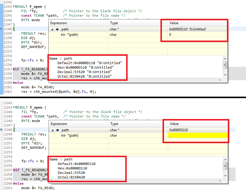
Any ideas on what could possibly going on here? It seems to me like it is more than just a code issue but I'm not an expert.
Keith,
Hrmm.....
It looks like the pointer to the path string is the same, but the value at said pointer changes. This leaves two options:
Try bumping up your stack size by a few hundred bytes and see if the behavior improves. Stack size may be adjusted in the build properties, linker options.
Trey
There seems to be some mighty fishy things going on with this program. Let me provide you some information and see if any of this might give you a clue or throw up a red flag.
First: in order to make the program fit on the chip I was force to edit the linker file to make more room. Seeing that RAML2 wasn't being used by anything, I commented that line out of the linker file and increased the space for RAML1 by 0x1000 (making the total size 0x2000). This provided the space needed for the "code" of the program.
Second: when running the program, I will always get a successful read of the file the first time it is run. If, within the program, I attempt to call f_open I get the behavior seen above. If I restart the device in the debugger (using the "Restart" button) I get the same results from f_open as if I had already called it once before (valid pointer location with bad data where the pointer is pointing). The only way I can make f_open behave properly is to restart the debugger.
Finally: I increased the stack memory to 0x600 and moved .stack in the linker command file to RAML6 (not being used by anything else) from RAMM1 and am still getting garbage results. This time I'm at least getting information at the location of the pointer but it's still bad data : "L\261"L\261"L\261". Additionally, I would think that if there was a problem with the stack overflowing that it would be encountered at one of the deeper function calls within FatFS, not at the highest-level function... But maybe I'm missing something?
Have I messed up the way this device operates by tweaking the linker file or is there something else going on here?
Keith,
No you haven't messed anything up...you just don't fully understand what is going on (and I mean that in the nicest way possible :-) ).
1) Good job moving stuff around in the linker file. Commenting out RAML2 and adding its space to L1 is a perfectly valid way to increase the memory for a section.
2) This is the KEY!!!! After restarting the program doesn't work! This says that the path you are passing is located in RAM and is loaded along with the program by the emulator. At some point the path data is getting overwritten and then on the next iteration the application fails to run correctly.
3) 0x600 should be more than enough stack space. I guess its not a problem with the stack.
Ok at this point I'd like to see a few things. Please post your linker command file as well as where you declare and define the path you are calling f_open with. I'll take a look and then get back to you.
Trey
linker file:
/*
// TI File $Revision: /main/11 $
// Checkin $Date: April 15, 2009   09:57:28 $
//###########################################################################
//
// FILE:    28335_RAM_lnk.cmd
//
// TITLE:   Linker Command File For 28335 examples that run out of RAM
//
//          This ONLY includes all SARAM blocks on the 28335 device.
//          This does not include flash or OTP.
//
//          Keep in mind that L0 and L1 are protected by the code
//          security module.
//
//          What this means is in most cases you will want to move to
//          another memory map file which has more memory defined.
//
//###########################################################################
// $TI Release:   $
// $Release Date:   $
//###########################################################################
*/

/* ======================================================
// For Code Composer Studio V2.2 and later
// ---------------------------------------
// In addition to this memory linker command file,
// add the header linker command file directly to the project.
// The header linker command file is required to link the
// peripheral structures to the proper locations within
// the memory map.
//
// The header linker files are found in <base>\DSP2833x_Headers\cmd
//
// For BIOS applications add:      DSP2833x_Headers_BIOS.cmd
// For nonBIOS applications add:   DSP2833x_Headers_nonBIOS.cmd
========================================================= */

/* ======================================================
// For Code Composer Studio prior to V2.2
// --------------------------------------
// 1) Use one of the following -l statements to include the
// header linker command file in the project. The header linker
// file is required to link the peripheral structures to the proper
// locations within the memory map                                    */

/* Uncomment this line to include file only for non-BIOS applications */
/* -l DSP2833x_Headers_nonBIOS.cmd */

/* Uncomment this line to include file only for BIOS applications */
/* -l DSP2833x_Headers_BIOS.cmd */

/* 2) In your project add the path to <base>\DSP2833x_headers\cmd to the
   library search path under project->build options, linker tab,
   library search path (-i).
/*========================================================= */

/* Define the memory block start/length for the F28335
   PAGE 0 will be used to organize program sections
   PAGE 1 will be used to organize data sections

   Notes:
         Memory blocks on F28335 are uniform (ie same
         physical memory) in both PAGE 0 and PAGE 1.
         That is the same memory region should not be
         defined for both PAGE 0 and PAGE 1.
         Doing so will result in corruption of program
         and/or data.

         L0/L1/L2 and L3 memory blocks are mirrored - that is
         they can be accessed in high memory or low memory.
         For simplicity only one instance is used in this
         linker file.

         Contiguous SARAM memory blocks can be combined
         if required to create a larger memory block.
*/


MEMORY
{
PAGE 0 :
   /* BEGIN is used for the "boot to SARAM" bootloader mode      */

   BEGIN      : origin = 0x000000, length = 0x000002     /* Boot to M0 will go here                      */
   RAMM0      : origin = 0x000050, length = 0x0003B0
   RAML0      : origin = 0x008000, length = 0x001000
   RAML1      : origin = 0x009000, length = 0x002000
//   RAML2      : origin = 0x00A000, length = 0x001000
   RAML3      : origin = 0x00B000, length = 0x001000
   ZONE7A     : origin = 0x200000, length = 0x00FC00    /* XINTF zone 7 - program space */
   CSM_RSVD   : origin = 0x33FF80, length = 0x000076     /* Part of FLASHA.  Program with all 0x0000 when CSM is in use. */
   CSM_PWL    : origin = 0x33FFF8, length = 0x000008     /* Part of FLASHA.  CSM password locations in FLASHA            */
   ADC_CAL    : origin = 0x380080, length = 0x000009
   RESET      : origin = 0x3FFFC0, length = 0x000002
   IQTABLES   : origin = 0x3FE000, length = 0x000b50
   IQTABLES2  : origin = 0x3FEB50, length = 0x00008c
   FPUTABLES  : origin = 0x3FEBDC, length = 0x0006A0
   BOOTROM    : origin = 0x3FF27C, length = 0x000D44


PAGE 1 :
   /* BOOT_RSVD is used by the boot ROM for stack.               */
   /* This section is only reserved to keep the BOOT ROM from    */
   /* corrupting this area during the debug process              */

   BOOT_RSVD  : origin = 0x000002, length = 0x00004E     /* Part of M0, BOOT rom will use this for stack */
   RAMM1      : origin = 0x000400, length = 0x000400     /* on-chip RAM block M1 */
   RAML4      : origin = 0x00C000, length = 0x001000
   RAML5      : origin = 0x00D000, length = 0x001000
   RAML6      : origin = 0x00E000, length = 0x001000
   RAML7      : origin = 0x00F000, length = 0x001000
   ZONE7B     : origin = 0x20FC00, length = 0x000400     /* XINTF zone 7 - data space */
}


SECTIONS
{
   /* Setup for "boot to SARAM" mode:
      The codestart section (found in DSP28_CodeStartBranch.asm)
      re-directs execution to the start of user code.  */
   codestart        : > BEGIN,     PAGE = 0
   ramfuncs         : > RAML0,     PAGE = 0
   .text            : > RAML1,     PAGE = 0
   .cinit           : > RAML0,     PAGE = 0
   .pinit           : > RAML0,     PAGE = 0
   .switch          : > RAML0,     PAGE = 0

   .stack           : > RAML6,     PAGE = 1		// M1
   .ebss            : > RAML4,     PAGE = 1
   .econst          : > RAML5,     PAGE = 1
   .esysmem         : > RAMM1,     PAGE = 1

   IQmath           : > RAML1,     PAGE = 0
   IQmathTables     : > IQTABLES,  PAGE = 0, TYPE = NOLOAD

   /* Uncomment the section below if calling the IQNexp() or IQexp()
      functions from the IQMath.lib library in order to utilize the
      relevant IQ Math table in Boot ROM (This saves space and Boot ROM
      is 1 wait-state). If this section is not uncommented, IQmathTables2
      will be loaded into other memory (SARAM, Flash, etc.) and will take
      up space, but 0 wait-state is possible.
   */
   /*
   IQmathTables2    : > IQTABLES2, PAGE = 0, TYPE = NOLOAD
   {

              IQmath.lib<IQNexpTable.obj> (IQmathTablesRam)

   }
   */

   FPUmathTables    : > FPUTABLES, PAGE = 0, TYPE = NOLOAD

   DMARAML4         : > RAML4,     PAGE = 1
   DMARAML5         : > RAML5,     PAGE = 1
   DMARAML6         : > RAML6,     PAGE = 1
   DMARAML7         : > RAML7,     PAGE = 1

   ZONE7DATA        : > ZONE7B,    PAGE = 1

   .reset           : > RESET,     PAGE = 0, TYPE = DSECT /* not used                    */
   csm_rsvd         : > CSM_RSVD   PAGE = 0, TYPE = DSECT /* not used for SARAM examples */
   csmpasswds       : > CSM_PWL    PAGE = 0, TYPE = DSECT /* not used for SARAM examples */

   /* Allocate ADC_cal function (pre-programmed by factory into TI reserved memory) */
   .adc_cal     : load = ADC_CAL,   PAGE = 0, TYPE = NOLOAD

}

/*
//===========================================================================
// End of file.
//===========================================================================
*/
Main program:
// TI File $Revision: /main/2 $
// Checkin $Date: July 30, 2009   18:45:34 $
//###########################################################################
//
// FILE:   Example_2833xSpi_FFDLB.c
//
// TITLE:  DSP2833x Device Spi Digital Loop Back program.
//
// ASSUMPTIONS:
//
//    This program requires the DSP2833x header files.
//
//    This program uses the internal loop back test mode of the peripheral.
//    Other then boot mode pin configuration, no other hardware configuration
//    is required.
//
//    As supplied, this project is configured for "boot to SARAM"
//    operation.  The 2833x Boot Mode table is shown below.
//    For information on configuring the boot mode of an eZdsp,
//    please refer to the documentation included with the eZdsp,
//
//       $Boot_Table:
//
//         GPIO87   GPIO86     GPIO85   GPIO84
//          XA15     XA14       XA13     XA12
//           PU       PU         PU       PU
//        ==========================================
//            1        1          1        1    Jump to Flash
//            1        1          1        0    SCI-A boot
//            1        1          0        1    SPI-A boot
//            1        1          0        0    I2C-A boot
//            1        0          1        1    eCAN-A boot
//            1        0          1        0    McBSP-A boot
//            1        0          0        1    Jump to XINTF x16
//            1        0          0        0    Jump to XINTF x32
//            0        1          1        1    Jump to OTP
//            0        1          1        0    Parallel GPIO I/O boot
//            0        1          0        1    Parallel XINTF boot
//            0        1          0        0    Jump to SARAM	    <- "boot to SARAM"
//            0        0          1        1    Branch to check boot mode
//            0        0          1        0    Boot to flash, bypass ADC cal
//            0        0          0        1    Boot to SARAM, bypass ADC cal
//            0        0          0        0    Boot to SCI-A, bypass ADC cal
//                                              Boot_Table_End$
//
// DESCRIPTION:
//
//    This program is a SPI example that uses the internal loopback of
//    the peripheral.  Interrupts are not used.
//
//    A stream of data is sent and then compared to the recieved stream.
//
//    The sent data looks like this:
//    0000 0001 0002 0003 0004 0005 0006 0007 .... FFFE FFFF
//
//    This pattern is repeated forever.
//
//          Watch Variables:
//                sdata - sent data
//                rdata - received data
//
////###########################################################################
// Original Author: S.S.
//
// $TI Release: 2833x/2823x Header Files V1.32 $
// $Release Date: June 28, 2010 $
//###########################################################################


#include "DSP28x_Project.h"     // Device Headerfile and Examples Include File
#include "functions.h"
#include "ff.h"

// Prototype statements for functions found within this file.
// interrupt void ISRTimer2(void);
//void delay_loop(void);
//void spi_xmit(Uint16 a);
//void spi_fifo_init(void);
//void spi_init(void);
//void error(void);
//void delayms(Uint16 time);
//void setPos(Uint16 pos);
//void clearScreen(void);
FRESULT Openfile(void);

FRESULT fresult;
BYTE Buff[1000];
UINT blen = sizeof(Buff);

void main(void){
//   Uint16 sdata;  // send data
//   Uint16 rdata = 0;  // received data

// Step 1. Initialize System Control:
// PLL, WatchDog, enable Peripheral Clocks
// This example function is found in the DSP2833x_SysCtrl.c file.
   InitSysCtrl();

// Step 2. Initalize GPIO:
// This example function is found in the DSP2833x_Gpio.c file and
// illustrates how to set the GPIO to it's default state.
// InitGpio();  // Skipped for this example
// Setup only the GP I/O only for SPI-A functionality
// This function is found in DSP2833x_Spi.c
//   InitSpiaGpio();

// Step 3. Clear all interrupts and initialize PIE vector table:
// Disable CPU interrupts
   DINT;

// Initialize PIE control registers to their default state.
// The default state is all PIE interrupts disabled and flags
// are cleared.
// This function is found in the DSP2833x_PieCtrl.c file.
   InitPieCtrl();

// Disable CPU interrupts and clear all CPU interrupt flags:
   IER = 0x0000;
   IFR = 0x0000;

// Initialize the PIE vector table with pointers to the shell Interrupt
// Service Routines (ISR).
// This will populate the entire table, even if the interrupt
// is not used in this example.  This is useful for debug purposes.
// The shell ISR routines are found in DSP2833x_DefaultIsr.c.
// This function is found in DSP2833x_PieVect.c.
   InitPieVectTable();

// Step 4. Initialize all the Device Peripherals:
// This function is found in DSP2833x_InitPeripherals.c
// InitPeripherals(); // Not required for this example
   spi_fifo_init();	  // Initialize the Spi FIFO
//   spi_init();		  // init SPI

// Step 5. User specific code:
// Interrupts are not used in this example.
//   Uint32 i = 0;

/*   Gpio_setup();
   Screen_Init();

   CS = 0;
   delayms(1);
   Write_Command(0x28);			// set display OFF
   Window_Set(0x0000, 0x031F, 0x0000, 0x01DF);
   Clear_Screen();				// make display black
   Write_Command(0x29);			// set display on   */

   do
   {
   	   fresult = Openfile();
   }while(fresult == FR_OK);
   for(;;);
}

FRESULT Openfile(void)
{
	static FATFS g_sFatFs;
	static FIL g_sFileObject;
	FRESULT fresult;

	fresult = f_mount(0, &g_sFatFs);
	if(fresult != FR_OK)
		return fresult;
	fresult = f_open(&g_sFileObject, "0:Untitled.bmp", FA_READ);
	if(fresult != FR_OK)
		return fresult;
	fresult = f_read(&g_sFileObject, Buff, 1000, &blen);
	if(fresult != FR_OK)
		return fresult;
	fresult = f_close(&g_sFileObject);
	if(fresult != FR_OK)
		return fresult;
	fresult = f_mount(0, 0);
	if(fresult != FR_OK)
		return fresult;
	Buff[0] = Buff[1];
	return fresult;
}


// Step 7. Insert all local Interrupt Service Routines (ISRs) and functions here:

/*void error(void)
{
    asm("     ESTOP0");						// Test failed!! Stop!
    for (;;);
}*/

/*void spi_init(void)
{
	SpiaRegs.SPICCR.all =0x0007;	             // 8-bit words
	SpiaRegs.SPICTL.all =0x0002;    		     // Enable master mode, normal phase,
                                                 // enable talk, and SPI int disabled.
	EALLOW;
	SysCtrlRegs.LOSPCP.all = 0x07;
	EDIS;
	SpiaRegs.SPIBRR =0x007F;
	SpiaRegs.SPICCR.bit.CLKPOLARITY = 0;
	SpiaRegs.SPICTL.bit.CLK_PHASE = 0;
    SpiaRegs.SPICCR.bit.SPISWRESET = 1;			// Relinquish SPI from Reset
    SpiaRegs.SPICCR.bit.SPILBK = 1;
    SpiaRegs.SPIPRI.bit.FREE = 1;				// Set so breakpoints don't disturb xmission
} */

/*void spi_xmit(Uint16 a)
{
	a = a << 8;
    SpiaRegs.SPITXBUF=a;
} */

/*void spi_fifo_init()
{
// Initialize SPI FIFO registers
    SpiaRegs.SPIFFTX.all=0xE040;
    SpiaRegs.SPIFFRX.all=0x204f;
    SpiaRegs.SPIFFCT.all=0x0;
}*/

//===========================================================================
// No more.
//===========================================================================
Low-level functions like those found in mmc-c28x.c and 6445F2806x_Spi.c are in the file functions.c. The rest of the FatFS system and related items are the same. I'd be happy to upload whatever else you might need.
Thank you so much for your patient help thus far!